Other Designs
Barrels Design
Clover Leaf
Ellipsoidal Design
Ellipsoidal Modules
On Three Levels
Pentagonal Ring
Hexagonal Ring
6-segment Anulus
Torus Dwelling
Twin Daisy Dwelling
Yin-Yang Design
Multi-Petal Designs
Other Designs
This is my first of many possible designs for a futuristic shell structure to accommodate the system of connected activity spaces described in the Activity-Based Design article. It creates the physical dwelling-cum-workplace, which forms the nucleus of the experimental farmlet.
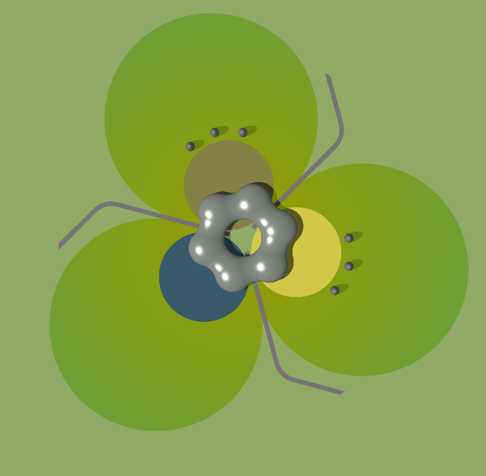 A plan (vertical) view of my landshare based Experimental Farmlet is shown on the right. The 2 landshare gleba comprises 3 circular areas of land that represent the wilderness, forest and grassland portions of the Earth's habitable land. The 3 smaller circles at the centre are two arable areas and a lake, which represent the arable and fresh water portions of the Earth's habitable land. At the very centre is a ring of 6 one-metre diameter concrete plinths. On these stands the 6-node shell of the integrated dwelling-cum-workplace at the centre of the farmlet. Click the image for a larger-scale view.
Below is an aerial view, from an elevation of 20°, of the whole gleba with the dwelling, service silos, lake and crop areas in the middle.
The following illustration shows a closer view of the dwelling at the centre of the gleba. The shell is made up essentially of 6 circular ellipsoids 16 metres diameter by 8 metres high. These are seamlessly joined by connecting passages. Each passage has the shape of the central section of a toroid which has been squashed to give it an elliptical cross-section.
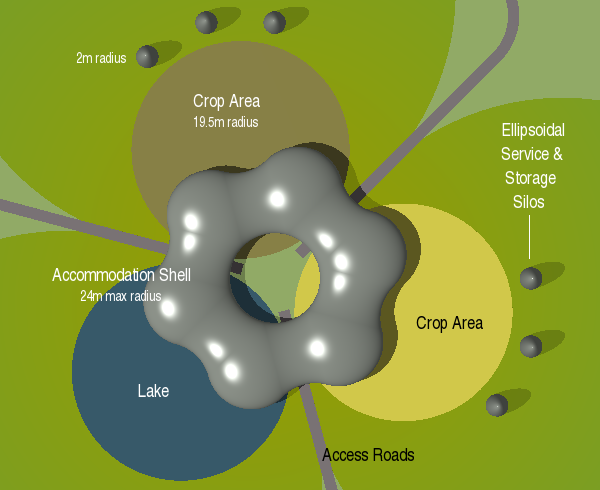
The integrated shell stands directly on the ground. Ground contact is at the lower points of the 6 ellipsoidal nodes. Each node rests on one of the small plinths around the centre of the gleba. Floor level, inside the whole of the shell, is 3 metres above ground level. Set away from the dwelling just beyond each crop area are 3 service silos. Each of these has the form of a vertically elongated circular ellipsoid. Thus there are 6 silos in all. These contain extra service, storage and support facilities for the main dwelling-cum-workplace.
The lake is 39 metres diameter and one metre deep. Its bottom is covered with pebbles of various dark colours. The lake serves as a reflecting pool to augment the external view of the dwelling. It also serves as a source of cooling for the dwelling's alternative technology systems. Two of the support plinths are within the boundary of the lake. Two of the dwelling's ellipsoidal nodes are therefore positioned over the lake.
The dwelling has a central open area, which is 16 metres diameter. The two 39-metre diameter crop circles and the lake fall within the central open area of the dwelling. Thus is formed a small private interior garden containing a small part of the lake and two small crescents of crop area. The two small private crop crescents form a vegetable and herb garden for the dwelling.
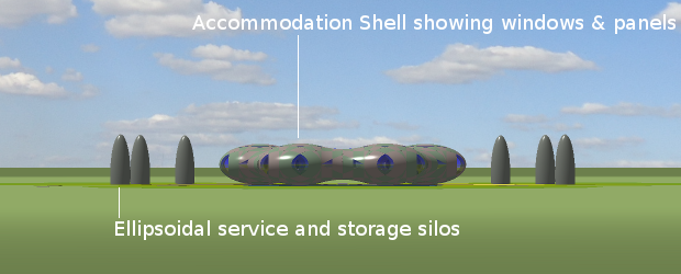
Below is a horizontal view of the dwelling. It shows side views of the central shell and the service/storage silos. It also gives a notion of how the central shell touches the ground at only 6 points, each point being the very bottom of each ellipsoidal node.
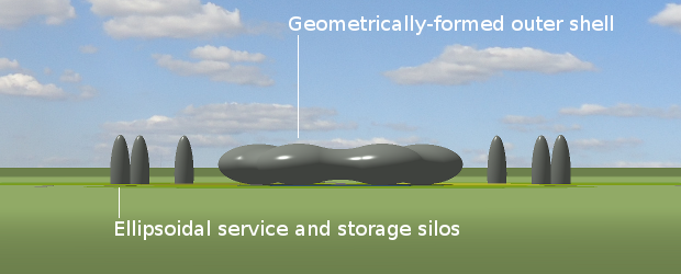
The ground clearance of the 6 highest points of the shell (under the connecting corridors) is only just over a metre. Consequently, neither people nor vehicles may pass beneath to enter the private inner garden.
Entrance to the shell is gained through a door at ground-level. The door is an opening section in the lower portion of the ellipsoidal node that contains the entrance hall. Access between ground level and the entrance hall (which is 3 metres above the ground) is by way of a helical staircase or lift. The stairs are 1 metre wide and make a three-quarter turn around a 2-metre diameter cylindrical lift-shaft. The stairs and lift are placed in a 4-metre diameter hole in the centre of the entrance hall floor. The lift takes both people and goods between the ground and the main floor level. The shell has a 3-metre diameter skylight at the top centre of each node. There are windows in other places as appropriate to the requirements of the internal space.
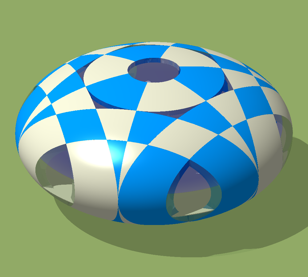 To facilitate on-site construction, the shell is divided into pre-fabricated panels. There are many patterns according to which the shell could be divided. The way I have chosen, for reason of illustration, is shown on the right. This is a view of one of the 6 ellipsoidal nodes from an elevation of 30°. The panels, into which the shell is divided, are shown in contrasting colours for clarity. The central skylight and two of the peripheral droop-eye windows can be seen. For simplicity at this stage, the toroidal sections, joining it to the other nodes, have been omitted.
The process of dividing the ellipsoidal node unit into panels is as follows. All slicing is performed on a sphere, whose radius is the horizontal radius of the ellipsoid. When all slicing has been done, the finished object is scaled to half-size in the vertical axis only. Thus the sphere becomes a 2:1 circular ellipsoid. I therefore explain the slicing of the sphere, not the ellipsoid.
On the left of the following diagram is shown a vertical (or longitudinal) slice through the centre of the sphere. The sphere is sliced longitudinally in this way every 60° around its equator. This slicing can be visualized by looking at the 6 panels that surround the central skylight in the above illustration. The sphere is then sliced in a direction perpendicular to each longitudinal cut at a distance r1 from the vertical (north-south) axis of the sphere, and again at a distance r3.

The distance r1 is half the radius of the sphere. This cannot be varied because, geometrically, it is the only distance at which the toroidal passage can be seamlessly merged with the ellipsoid. The distance r3 was arbitrarily set at ¾ of the radius of the sphere because this is the radius that resulted in the droop-eye windows being about the size of the central skylight. The radial distance r2, although geometrically relevant, was discarded, as it did not result in useful slicing.
Circular (latitudinal) cuts are made around the central skylight and also at radius r1 from the vertical axis of the sphere. All this slicing results in the pattern of panels shown in the last-but-one diagram above on the right.
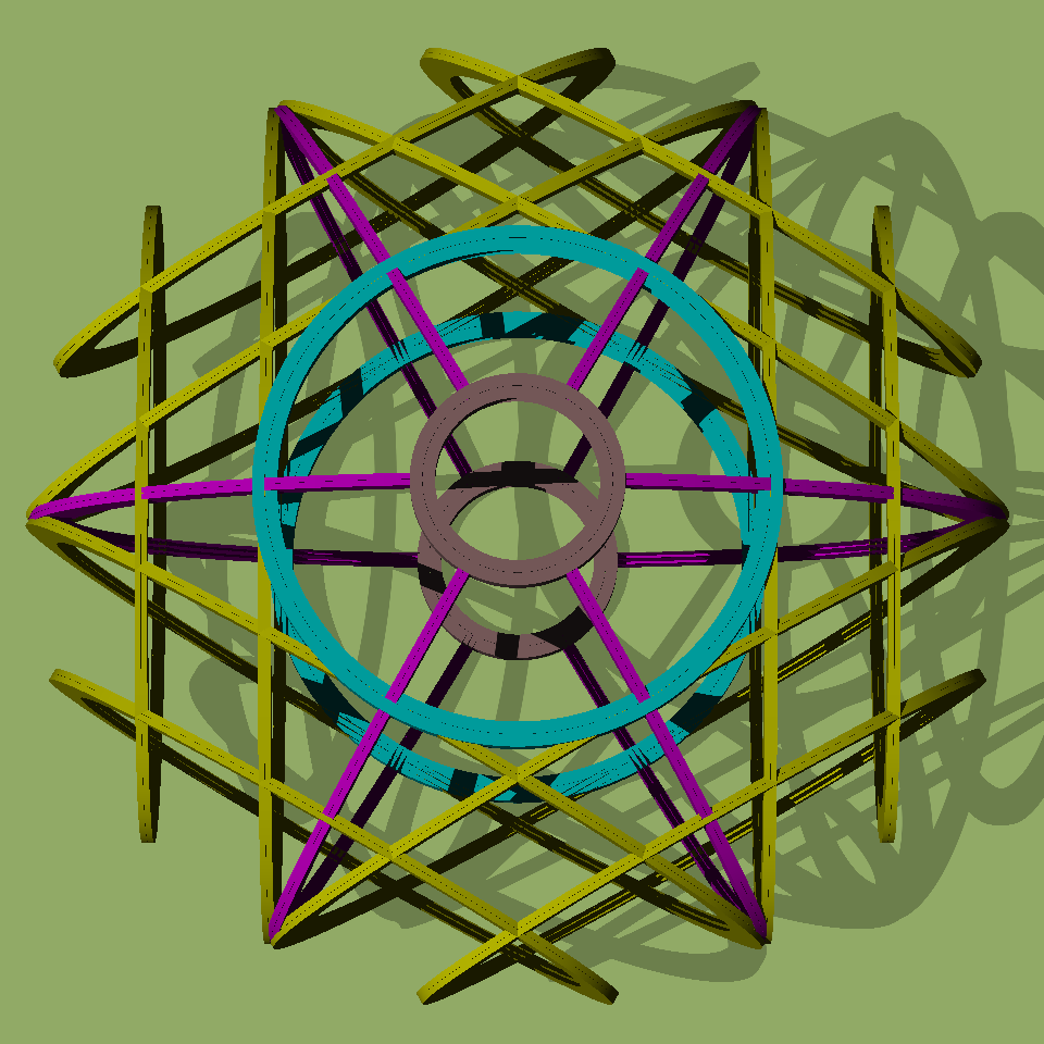 Each panel is surrounded on all sides by flanges. These facilitate the connection of the panel to its neighbours. The windows also have flanges and have exactly the same form as panels, the only difference being the material of which they are made. A view of the flange system of an ellipsoidal node is shown on the left from an elevation of 80°. To aid illustration, the width and thickness of the flanges have been exaggerated. Flanges that run in the horizontal plane are circular. Flanges that run in the vertical plane are elliptical. The different flanges are shown in contrasting colours for clarity.
Each flange-circle or ellipse, as shown in the above illustration, comprises two circular (or elliptical) annuli 4mm apart. The diametric thickness of the circular flange rings is 500mm. The diametric thickness of the elliptical flange rings varies between 250mm (at the top and bottom of the node) and 500mm (around its periphery). When the panels are bolted together, a gasket — which compresses to 4mm thick — is placed between their flanged sides. The gaskets are sealed on the outer surface of the dwelling with non-setting gasket grouting.
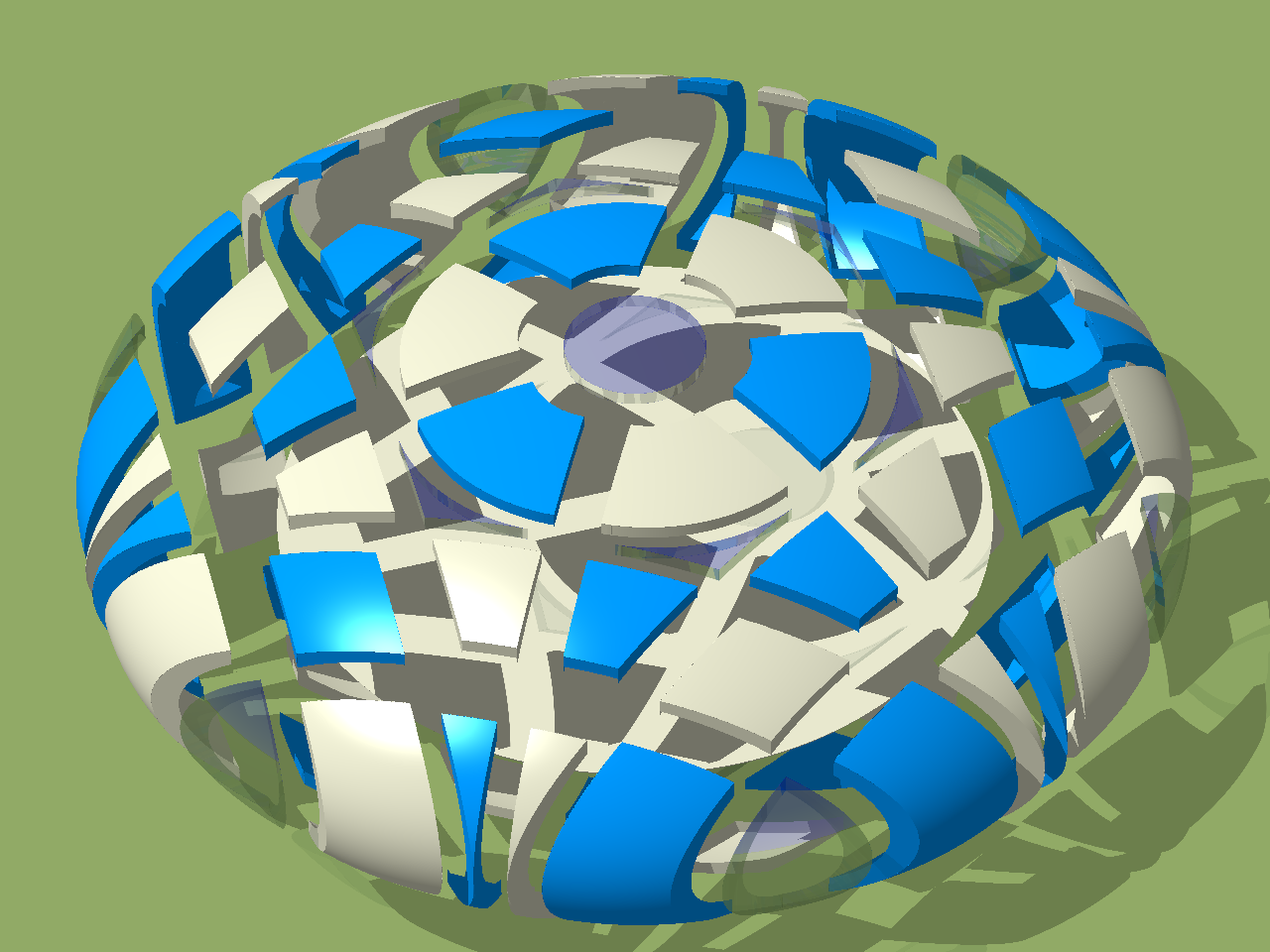 An exploded view of the panels, which make up a complete ellipsoidal node, is shown on the right. The flanged sides of the panels can be seen. The circular floor of the node can also be seen through the gaps between the panels. In this illustration, the panels have been moved outwards radially from the central vertical axis of the ellipsoid in the horizontal sense only. A special scaffolding-type jig is used for support during construction while the panels are being joined.
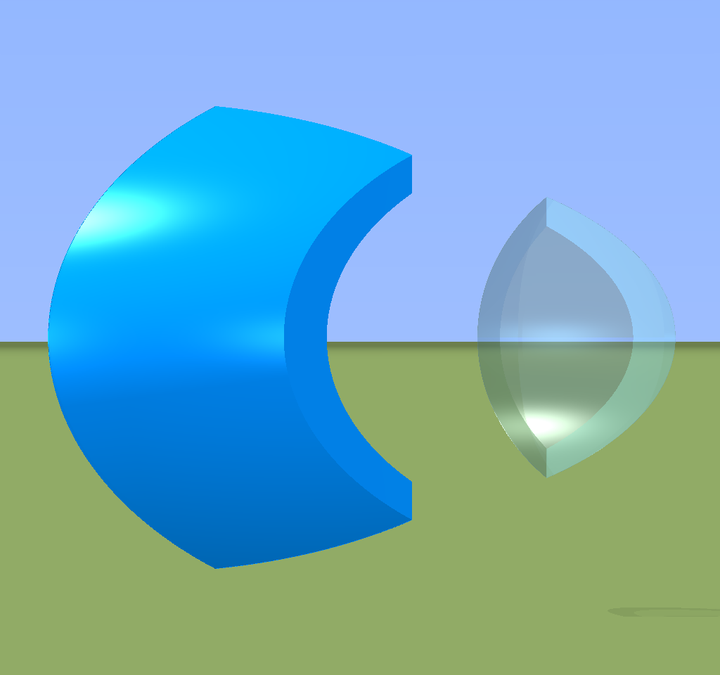 Each panel may be displayed in isolation. Two examples are shown on the left. One is the transparent droop-eye window. The other is an opaque panel which adjoins the droop-eye window on the periphery of the ellipsoidal unit. The shape of a panel is generated mathematically. Consequently, it can be rendered at any size up to the full precision of the rendering program. The numerical data from which the image is rendered is then directed to a 3-D printer to form a solid version of the panel, which is used to create a mould or jig to reproduce the panel in the desired material.
The mould or jig for each panel is formed in wood or polystyrene as a "negative" of the panel as "printed" by the 3-D printer. The panels are made of a strong fibre-plastic which can be concocted from ingredients that occur naturally within the wild. This material comprises successive layers of woven natural fibres held together by a natural glue mixed with an agent to render it non-flammable. The panels are bolted together with intervening gaskets of natural fibre to form the complete six-node shell. Any section which may suffer damage in the future may be unbolted and replaced independently. Certain panels have hexagonal photovoltaic tiles embedded in their outer surfaces to provide some of the farmlet's electricity.
All opaque panels are produced to a completely finished state off-site before construction begins. This includes an in-fill unit, which fills the inner surface of the panel to the extent of its flanges. The in-fill unit contains high-grade thermal insulation and an inner upholstered sound-damping surface. It also includes conduit passages for wiring and piping the finished dwelling.
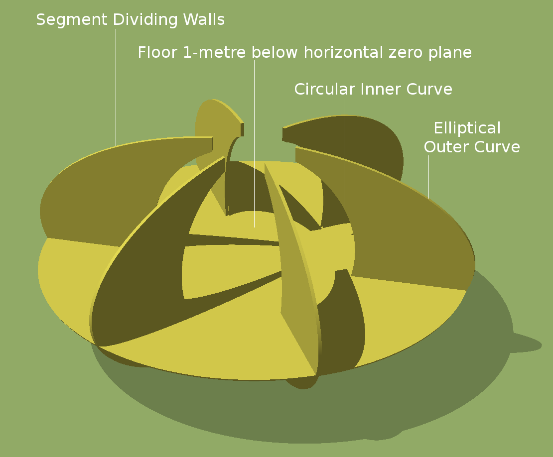 The internal space of each nodal module is divided into a central 8-metre diameter circular area, surrounded by 6 peripheral segments. Each opposing pair of the 6 dividing walls has a vertical profile of an ellipse (16 metres across by 8 metres high) with a central circular cut-out of 7½ metres diameter. A further central cylinder the diameter of the central skylight is also cut out. The full assembly of floor and dividing walls is shown on the right. It is perhaps better viewed in a larger scale.
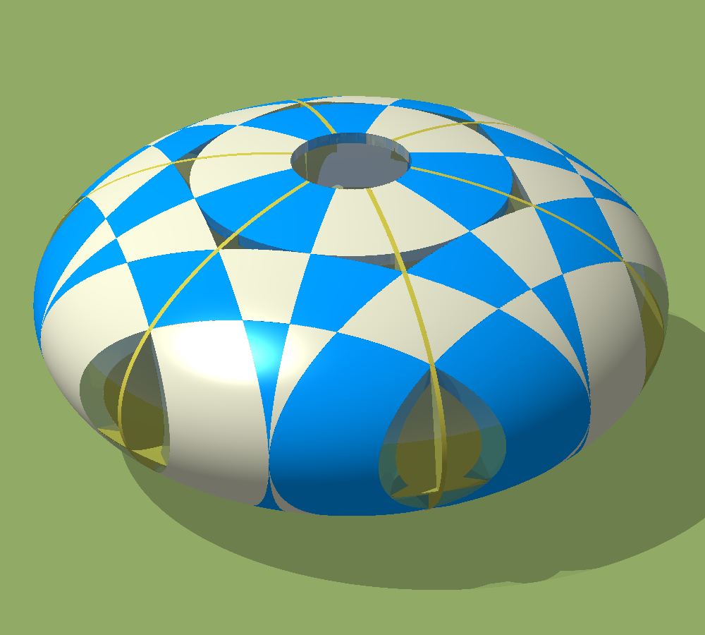 The illustration on the left shows how the internal dividing walls lie relative to the panels which comprise the outer shell. The dividing walls (shown in yellow) do not really protrude the surface of the panels. The yellow lines on the outer surface of the shell are there merely to illustrate where the walls lie inside the shell. The inner walls do not follow the paths of any of the panel flanges. They are, however, fastened to the panels they touch and are thus used as the guiding structure for assembling each node of the dwelling.
 The 6 ellipsoidal modules, which form the complete dwelling of the farmlet, are joined together by 6 toroidal corridors. Each corridor merges smoothly with two adjoining modules along the elliptical flange at distance r1 from the vertical axis of each module. The merging line is illustrated on the right by a transparent semi-corridor section, which is shown joined to a normal ellipsoidal module. The panels, which are visible within the glass semi-corridor, are there for illustration only. They do not exist in the finished construction.
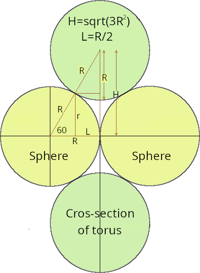 The form of the toroidal section, according to which the corridors are constructed, is illustrated on the left. The minor-radius of the torus R is the same as the radius of the sphere from which the ellipsoidal modules are formed. The area shaded in light grey is a quarter cross-section of a full corridor. The full length of the corridor is the same as the radius R of the sphere. A full corridor (that required to span the full length between two adjacent modules) is formed by having the torus clipped by a cylinder of radius R and length R and whose centre and axis are coincident with those of the torus. The major radius of the torus H = R × tan(60°). The critical dimension in the design of the whole farmlet dwelling is the clearance height between the lowest part of the corridor and the floor, which is ½(H−R)+1 metres.
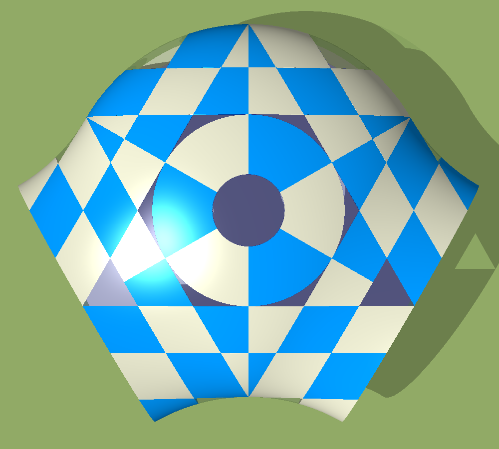 Each ellipsoidal module has two integrated semi corridors 120° apart, as shown on the right. The panels beyond two of the three sides of the triangle (that is formed by the three elliptical flanges at distance r1 from the vertical axis of the ellipsoid) are, in effect, lopped off and replaced with the two semi corridors. Six of these integrated units fit together to form the complete farmlet dwelling. To complete the panel cutting of the corridor sections, an extra tangential cut at distance R from the central vertical axis of the ellipsoid is required.
There is no direct access to the inner garden of the dwelling from the outside world, except by stooping down and crawling under the 1-metre clearance below the connecting corridor sections. However, this would entail going in the lake or through crops.
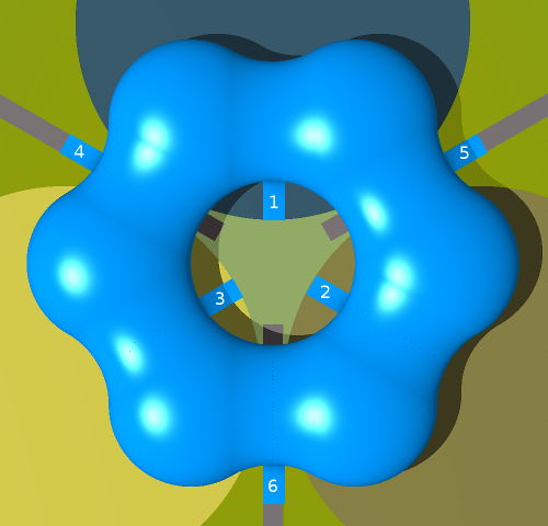 Access from the dwelling into the inner garden is via 3 drop-down stair ramps labelled 1, 2 and 3 in the adjacent illustration. These let down across the two crop circles and the lake as shown. The one that lets down across the lake is only for emergency use, as it leads from the space in between the two bedrooms.
Access into the dwelling from the outside world is via 3 drop-down stair ramps labelled 4, 5 and 6 in the illustration on the left. These let down onto each of the 3 roads which terminate at the dwelling.
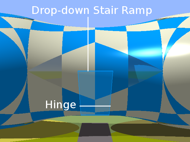 Each drop-down stair ramp is two metres wide and 6548 millimetres long. It is hinged a quarter of its length from the bottom mid-point of the connecting corridor. The lowering and raising of the ramps is motorized. Sensors on the ramps detect obstacles (especially human beings) and will halt if there is any danger of trapping any object or person. When raised, the stair ramps form a part of the profile of the dwelling's shell.
The complete dwelling in its farmlet setting is shown below. In this view, all the opaque panels are shown in the same standard colour. Only the windows appear different in that they are made of a transparent material such as glass or laminated perspex. The dwelling can, of course, have whatever surface finish its owner may desire. It could be covered in any pattern from forest camouflage to exotic floral, to the highly decorative Julia or Mandelbrot sets from Chaos Theory. The desired surface finish is put on the panels off-site at fabrication time before construction begins.
The following ground view, taken from the direction of the lake, shows the whole farmlet with the dwelling panels in two low-contrast camouflage colours. I think the droop-eye windows add an air of beautiful enigmatic mystery to its appearance.
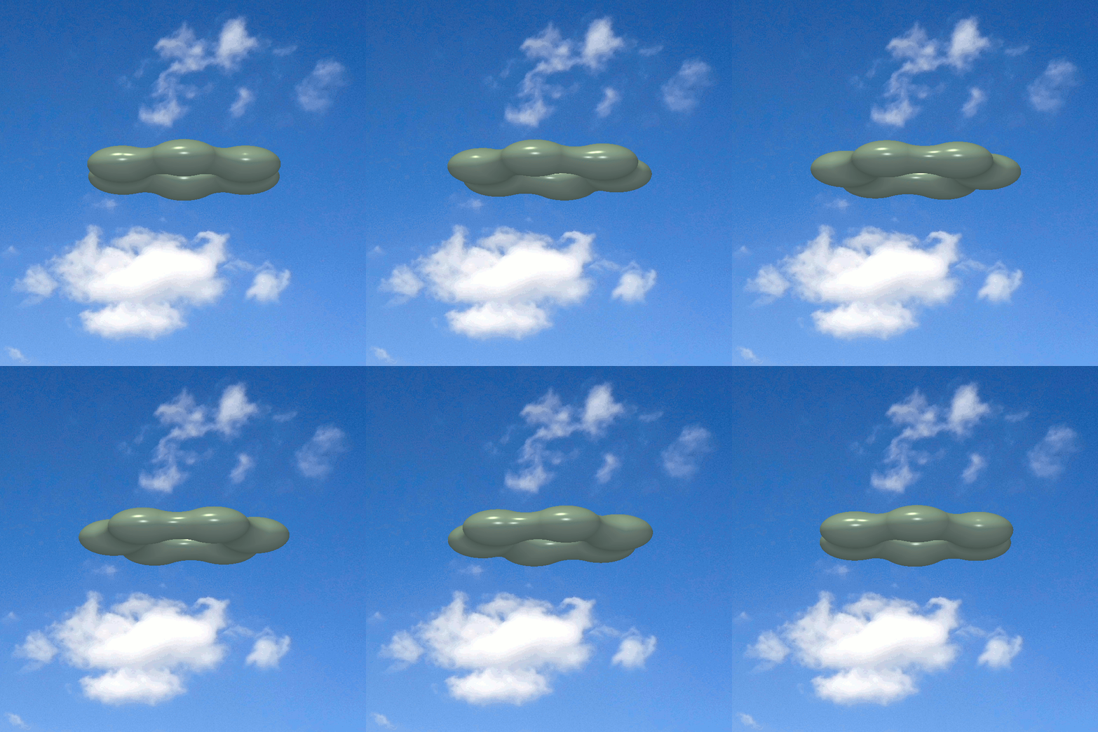 In a landshare-based society, there's a practical advantage — if not necessity — for being able to move to different landshare locations throughout one's lifetime. For this reason, I propose that, in this alternative world, homes should be essentially vehicular. They must be able to relocate easily. They do not need to move frequently. Nor do they need to travel at great speed. Preferably, such a home should, for the duration of a move, become a kind of airborne vehicle that can move easily and safely under its own power and guidance, with the ability to avoid collisions with fixed obstacles and other airborne vehicles.
All views of the farmlet and its central dwelling in this article were generated using POV-Ray 3.6 from mathematical specifications of the shapes involved. See the relevant povray script file for details. Over many years I have played around with many other designs [see side panel] for the farmlet dwelling.