Before you can run this program you must first compile it from the source code. Create a new directory called 'nav' in a convenient place. Download the file nav.7z. Move it to your new directory 'nav'. Unzip the nav.7z file. The zip file contains the source code 'nav.c' plus the routes data files. If you are running 64-bit Linux, the executable program 'nav' is already there, so you do not need to compile the program from source. If not, open 'nav.c' in a text editor. I prefer gedit because of its good source highlighting. Open a terminal. Do a 'cd' to your new directory. The compiling and running instructions are near the beginning of the source listing. Simply copy and paste them into your terminal and press 'Enter'.
This program is controlled entirely by the mouse. It has no keyboard input. It outputs only to the screen and also optionally to 'stdout'. It reads route information from text files and can, under certain circumstances, take input from 'stdin'. It does not write to disk: it has no output files, although you may redirect 'stdout' to a text file of your choice via the command line if you wish.
Global Navigator II has a small [500 x 400 pixel] window area but its content is distributed across 8 tabs. The different tabs are selected by clicking on the respective tab buttons across the top of the window area.
Modes of Operation
The program is designed to run in one of 3 different situations: in isolation, with output-only, or with input and output.
When running in isolation, the program is merely a demonstrator, which flies a fictitious aircraft from the selected route's prescribed origin to its prescribed destination, with or without internally-simulated wind. To start the program in this mode, open a terminal, go to the directory containing the program 'nav' plus its route files and enter the command './nav'.
When running with output only, the program additionally outputs its heading, speed and height commands to 'stdout'. To start the program in this mode, enter the command './nav -o'. If you would like to collect the output in a text file for later analysis, you can re-direct the output from 'stdout' to a file by entering the command './nav -o > output.txt', where 'output.txt' is the name of the file containing the output. Note that clicking the 'CMD TO STDOUT' button once the program has been started in isolation mode sends output to 'stdout' but this cannot in this circumstance be re-directed to a file.
The third situation [with input and output] is quite different from the other two. In this situation, the program is part of a control loop that can be flying a real air vehicle or a simulated vehicle in an environment that is external to the program. In this situation, the program receives input of the air vehicle's real-world latitude and longitude via 'stdin' at regular intervals of 1 second, 200 milliseconds or 40 milliseconds as required. It then computes and outputs the heading, speed and height commands required to navigate the air vehicle, from its origin to its destination, along the selected route.

In the above illustration, pos is a program that supplies the air vehicle's live latitude and longitude, which it acquires from a hardware interface connected to an external GPS, radio aids receiver, inertial platform or Moon Tracker. This program, nav, uses this input to compute and then output the requisite flight commands to the program apt, which passes them via another hardware interface to an external autopilot or flight director computer. To set up this situation enter the command:
./pos -io | ./nav -io | ./apt -io
Of course, this is strictly a test-bed development situation. It is not safe to fly real air vehicles by software running under a conventional operating system. For real flight control, the software must be integrated in read-only memory within dedicated hardware. Note: to terminate the above pipe command, enter Ctrl-C in the terminal.
Program Structure
The main() function of this program sets up and initialises the window and event listeners, then enters a permanent loop which is broken only by a click from the left mouse button on the X at the top right of the window. main()'s permanent loop triggers 3 different execution chains, respectively comprising what must be done:
-
upon initial exposure or re-exposure of the window
-
on receipt of a left-button mouse click from a menu or control button
-
once every clocked refresh cycle
On initial exposure of the window, the route names and the default route's waypoints are loaded and the aircraft data is initialised to the start of the route. The MAP tab is then drawn with the map plus all flight data and buttons in their initial default states.
On re-exposure — when the program window is returned from a minimised state or the user returns from having visited another desktop — the current state of the currently selected Tab is redrawn in its current state: NOT its default state. The routes are not reloaded in this case, as this would reset any flight that was in progress when the window was minimised or the user left the desktop on which the program is running.
The receipt of a mouse click from a menu or control button, calls the current Tab's mouse click handler, which selects and highlights the relevant menu item or control button and initiates the processing required by that selection.
Once every refresh rate period, if a flight is in progress, the updt functions are called to advance the aircraft along its route and re-display the updated situation.
Two items vital to this navigation program are the Vincenty position, distance and bearing functions VSGDP() and VSGIP(). Respectively, they compute:
the position [latitude and longitude] of a waypoint, given the position [latitude and longitude] of the aircraft, plus the distance and bearing of the waypoint from the point of view of the aircraft, and
the distance between a waypoint and the aircraft, plus the bearing of the waypoint from the point of view of the aircraft and the bearing of the aircraft from the point of view of the waypoint, given the positions [latitudes and longitudes] of the aircraft and the waypoint.
Note that the bearing of the waypoint from the point of view of the aircraft and the bearing of the aircraft from the point of view of the waypoint [in item 2. above] are two separately calculated angles. In the spherical geometry of the Earth's surface, one is not simply the reverse of the other. The bearing of the aircraft from the waypoint is not simply the bearing of the waypoint from the aircraft + 180°.
Formally, the first computation is known as the Solution to the Geodetic Direct Problem and the second is known as the Solution to the Geodetic Inverse Problem. The algorithmic solutions used in this program are those formulated by Thaddeus Vincenty in 1975. The direct VSGDP() and inverse VSGIP() functions used in this program are my transcodings into 'C' of FORTRAN versions by Lcdr. L. Pfeifer of NGS Rockville MD dated 20 February 1975. I have changed some of the names of the variables to conform more to the nomenclatures in the rest of the program.
The Vincenty functions use an ellipsoidal geodetic model of the planet. Notwithstanding, the Earth is not perfectly ellipsoidal. It is more pear-shaped, with the neck of the pear at the North Pole and the flattened bottom of the pear at the South Pole. Consequently, an ellipsoid that fits the earth's surface faithfully over one part of the globe isn't equally accurate in other parts of the globe. To resolve this problem various people and institutions at various times have constructed ellipsoidal models that fit their respective parts of the globe more accurately. Hence, this program has a Geoid Selection menu so that the user can select the geoid most appropriate to the part of the globe over which the current flight is passing. The program default is for the geodetic ellipsoid to be selected automatically according to the current position of the aircraft. However, as currently implemented, this is as yet not very comprehensive.
There are many sources on the Web giving detailed treatments of the methodology, geometry and computations involved in the Vincenty solutions.
The maximum number of iterations necessary for the Vincenty computations to converge, as recorded during the current program session, are displayed at the lower left of the WAYPTS tab [just because there was space there for them].
The two Vincenty methods are mathematical: they employ our fit-kit of special-case mathematical functions to try to relate the real shape of the Earth to a set of best-fit ellipsoids, which differ for different parts of the planet's surface. The Vincenty methods then go on to use an iterative process to gain further accuracy. These methods are complicated and therefore demand a lot of CPU time.
Each Vincenty method may be used to train a corresponding multilayer perceptron [MLP] over all the routes to be flown, each MLP could then replace its respective Vincenty function to provide position, distance and bearing information in a fraction of the time.
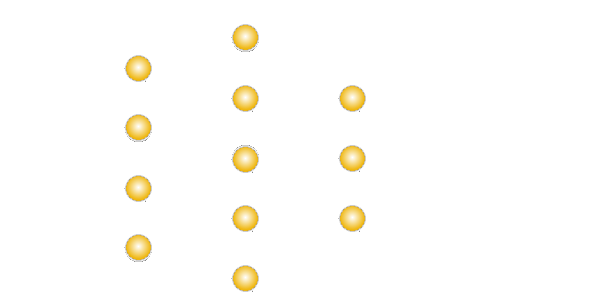
Shown above is is an MLP to resolve the Vincenty Direct [Forward] Geodetic Problem. Shown below is an MLP to resolve the Vincenty Inverse Geodetic Problem:
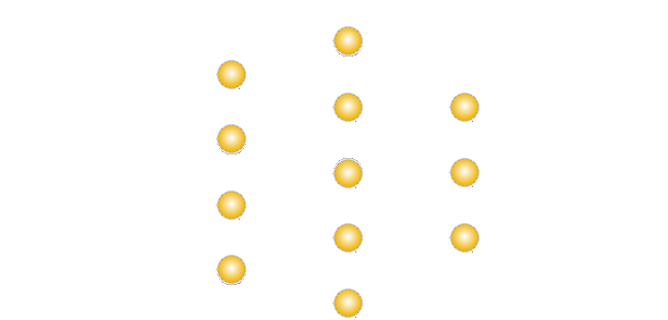
Each neuron contains circuitry to sum its inputs and a non-linear transfer function to produce its output. Each link joining neurons in the 3 layers has an adjustable impedance or 'weighting'. During its training phase, during each flight, the same inputs are fed to the MLP as are fed to the normal Vincenty function. Then the outputs of the MLP are compared with the outputs from the normal Vincenty function. The differences [errors] between the two are back propagated in the form of weight adjustments to all the links that join the neurons of the different layers. Eventually, the errors will diminish to almost nothing. The MLP is then trained and can be used in place of its corresponding normal Vincenty function to perform the task much more rapidly.
The simple MLPs shown in the diagrams each has only one hidden layer. Theoretically, any function can be simulated by a single hidden layer with sufficient neurons.
However, to compute the required outputs from the available inputs for any two points on our pear-shaped planet, from teaching data supplied by the two Vincenty methods switching, according to region, between different standard best-fit geoids, multiple narrower hidden layers should be more efficient.
An MLP is an analogue computing device, which is usually implemented as a digital simulation of an analogue MLP inside a digital computer. Once trained, it can be implemented as a single chip digital module.
When the program is started, the T2routes() function loads the file 'routes.txt'. This contains the names of all the available routes plus the take-off runway heading at the origin and landing runway heading at the destination for each route. The format of the data within each line of the file 'routes.txt' is illustrated by the following example:
224 161 Stansted to Belo Horizonte
The two 3-digit numbers at the beginning of the line are respectively the runway headings [in degrees] of the origin and destination airports. The remainder of the line is the name of the route, which comprises the names of the origin and destination airports.
Once it has loaded 'routes.txt', the program loads the waypoints data pertaining to the default route.
The name of a waypoints data file comprises the word "route" followed by a 2-digit number [with leading zero if necessary] followed by the file name extension '.txt'. Route numbers start at '00'. Thus the name of the first waypoints data file is 'route00.txt'. The format of each line of a waypoints data file is illustrated by the following example:
* 186780 780 106 Stansted
If the initial character is an asterisk '*', the data line pertains to a waypoint within the route. If the initial character is a space, the item is simply a passive geographic feature, which will appear on the map as an additional visual reference. All waypoints must appear in route order from the beginning of the file. All passive geographic features must be added after the destination waypoint.
The 7 characters immediately following the asterisk [or space] specify the latitude of the waypoint. The next 8 characters specify the waypoint's longitude. Latitude and longitude are expressed in integral seconds of arc. The figures are preceded immediately by minus signs where necessary. The remainder of the field is padded, if necessary, with leading spaces: not zeros. The next 5 characters are the waypoint's elevation above sea level in metres [positive only]. The height field is also padded with leading spaces: not zeros. The remainder of the line, after the space, comprises the name of the waypoint, terminated with a 'new line' character.
Upon input, the latitude and longitude are converted to double-precision floating point values expressed in radians. They are stored, along with the other items of waypoint data, in an array of geographic feature and waypoint data structures.
You can create as many new routes as you wish in files with the generic name 'routeNN.txt', where NN is the route number. However, you must be sure to follow exactly the prescribed line format.
Initialising a Route
For each waypoint in the route, the bearing to the previous waypoint [the inbound radial] and the bearing to the next waypoint [the outbound radial] are then computed and stored. Of course, the first waypoint of a route has no inbound radial. Its take-off runway heading is an extension of what would otherwise be its inbound radial. Similarly, the destination waypoint has no outbound radial. Its landing runway heading is its outbound radial.
The geometry of the turning arc for each en-route waypoint is then constructed as shown in the following diagram. This involves computing the latitude & longitude of the centre of the turning circle, from its distance and bearing from the waypoint, using the Vincenty Direct function: VSGDP().
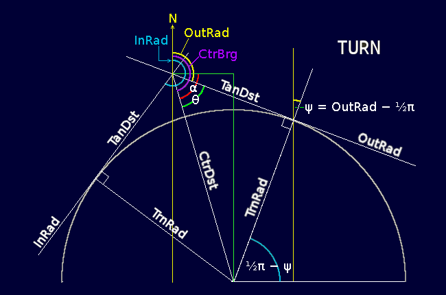
From this is computed the distance from the waypoint where the turning arc begins and ends, i.e. where the waypoint's inbound and outbound radials touch the turning circle tangentially. The latitude & longitude of the centre of the turning arc, plus the distance of the start of the turn from the waypoint along each radial, are stored as part of the waypoint's data for use later by the in-flight computations.
COMPUTED AT ROUTE LOAD TIME:
θ = 0·5 × (InRad − OutRad)
CtrDst = TrnRad / sin(θ)
CtrBrg = OutRad + θ
TanLim = √(CrtDst2 − TrnRad2)
Scan for [REF:TURNCTR] in 'nav.c'.
The core of this program is the updtTrack() function. This moves the aircraft along its route by the amount it would travel during each refresh-rate period. It performs the following tasks in the sequence shown:
Manage changeovers from the aircraft's encounter with its current waypoint to its encounter with the next waypoint en-route.
When receiving live inputs of real-world latitude & longitude of the aircraft via 'stdin', compute the positional error due to real-world wind drift and the consequential required correction to the aircraft's thrust heading.
Compute the distance and bearing of the current waypoint from the aircraft and update the TO/FROM status as necessary.
Compute the aircraft's new required heading according to whether the aircraft is travelling TO or FROM the current waypoint, is making a turn AT the current waypoint, or is flying trans-oceanic, beyond the 'radio range' of the current waypoint. Damp the rate of change of the computed required heading of the aircraft to create a smoothly incrementing/decrementing command heading.
Compute the aircraft's required air speed as a biased and capped non-linear function of its distance from its current waypoint, starting and finishing the journey smoothly at take-off and landing speed. Damp the rate of change of the computed required speed of the aircraft to create a smoothly incrementing/decrementing command speed.
Compute the anticipated distances the aircraft travelled (1) due to engine thrust and (2) due to wind drift, and from this derive the resulting new anticipated latitude & longitude of the aircraft after this pass of the program.
Compute the change in the required height of the aircraft during this pass of the program, according to a sigmoidal profile of the height difference between the current and next waypoints [the FROM situation] or previous and current waypoints [the TO situation]. Damp the rate of change of the computed required height of the aircraft to create a smoothly incrementing or decrementing command height.
When output mode is active, send live heading, speed & height commands to 'stdout'.
1. Waypoint Encounters
A flight, from an origin to a destination, comprises a series of encounters, in prescribed order, with the waypoints that make up the route being flown.
NOTE: the sample routes accompanying this program use cities as waypoints. Real air routes don't do this: they use radio aids stations or significant geographic features. Cities are used here for ease of perception because people do not generally know the locations of radio-navigation stations.
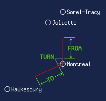 A waypoint encounter comprises three phases: a 'TO' phase, a 'TURN' phase and a 'FROM' phase. The example on the left shows the aircraft's encounter with the Montreal waypoint. The previous waypoint in the route is Hawkesbury. The next waypoint is Sorel-Tracy. The 'TO' phase of the Montreal encounter is from the half-way point between Hawkesbury and Montreal up to the point where the inbound radial touches the Montreal turning arc. The 'FROM' phase is from where the outbound radial touches the Montreal turning arc to the half-way point between Montreal and Sorel-Tracy.
The turning arc is a part of what is termed the 'turning circle'. The turning circle for all waypoints has a radius of 10,000 metres. It is located such that the inbound radial from the previous waypoint and the outbound radial to the next waypoint form tangents to it. During the 'TO' and 'FROM' phases of the encounter, the point of reference for the aircraft is the waypoint itself. However, during the 'TURN' phase, the aircraft's point of reference is switched to the centre of the turning circle. This is to avoid possible rogue values of distance and bearing as the aircraft passes very close to the waypoint.
At the start of a flight, the aircraft's encounter is with the initial waypoint [the origin airport]. The initialisation of this first encounter is done when the route's waypoints data are loaded and initialised or when a flight is RESET to the beginning. It is also done every time the aircraft, during a flight, passes the halfway point between two consecutive waypoints of the route. This task is performed in all these cases by the function initEncounter(). The first task of the updtTrack() function [item 1. above] is to call this function every time the aircraft passes the halfway point to the next en-route waypoint.
2. Heading Compensation for Wind
If this program is receiving the actual latitudes and longitudes of the aircraft as provided by sources such as GPS, inertial platform or ground-based radio aids, it uses the Vincenty Inverse function to get the distance and bearing of the real position of the aircraft from the point of view of where it was predicted to be from the previous calculation. It is assumed that this error is due to displacement of the aircraft by the wind. The corrected distance blown by the wind since the previous calculation is therefore: D = sqrt(X * X + Y * Y) as shown in the adjacent diagram. Scan for [REF:WIND] in 'nav.c'.
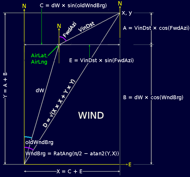
If the program is not receiving live positional data, the aircraft's latitude & longitude previously computed are used instead of the live input values. In this case, if simulated wind is switched on, the radial intercept functions bias the aircraft's heading automatically to compensate for the wind.
From this positional error, the program then computes the heading offset, that must be added to the aircraft's command heading, in order to compensate for this positional error. The vector geometry for this computation is shown in the adjacent diagram. Note that the diagram shows the case for the positive/positive quadrant only. However, the atan2() function used in the program takes care of all the +/- sign conditions for the 4 quadrants. The updtTrack() function then uses the received values of aircraft latitude and longitude to compute the required heading, command heading, speed and anticipated latitude and longitude to be used in the next pass of the program.
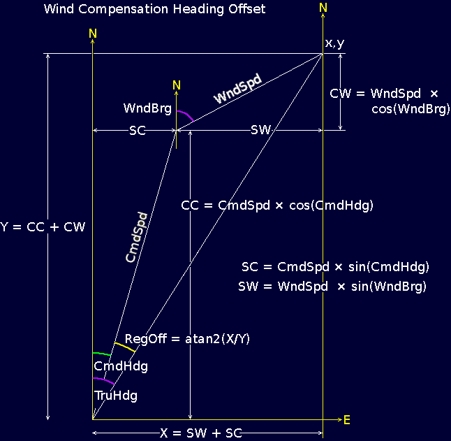
Note that, even if it is switched on, simulated wind is ignored if the program is receiving live latitude and longitude input.
3. Distance & Bearing and TO/FROM Status
The pivotal task in navigating the aircraft along its route is to compute the current distance [WptDst] between the aircraft and the waypoint it is currently referencing. Before it does this, however, the program notes and preserves the old distance [PreDst] computed during its previous pass.
The program then calls the Vincenty Inverse function [VSGIP()] to get the new distance [WptDst] and the forward and back bearings [FwdBrg and BakBrg]. As shown in the adjacent diagram, North at the aircraft is not the same direction as North at the waypoint, except where both are on the Equator. In the northern hemisphere the two North lines [lines of longitude] converge; whereas in the southern hemisphere they diverge. Consequently, the back bearing is not simply the forward bearing minus π/2 [180°]. Neither is the calculation a simple matter of spherical geometry: it requires an iterative convergence on an ellipsoidal geoid.
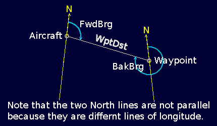
The newly computed distance between the aircraft and the waypoint are then compared. If the new distance is less than last time's distance, the aircraft is flying TO the waypoint: if the new distance is greater than the old distance, the aircraft is flying away FROM the waypoint. The program's 'TO' flag is set accordingly.
4. Compute Required Heading
Scan for [REF:TO/FROM] in 'nav.c'.
The 'TO' phase of the program computes the required heading [ReqHdg] which the aircraft must fly in order to remain on — or make an asymptotic approach to — the waypoint's INbound radial. The '0.49' in the formula at the top of the diagram is to ensure that the computed required heading is always less than π/2 [90°] from the inbound radial; i.e. the aircraft is always directed TOwards the waypoint; never away from it.
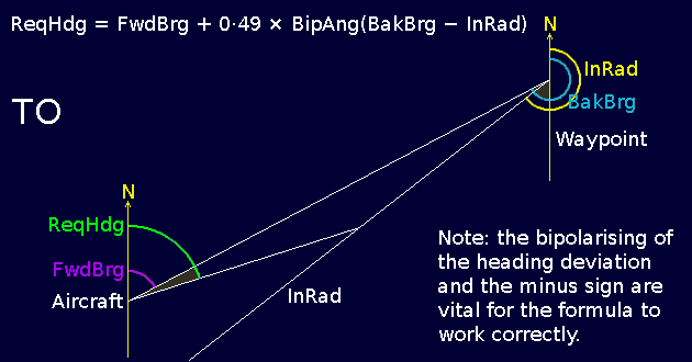
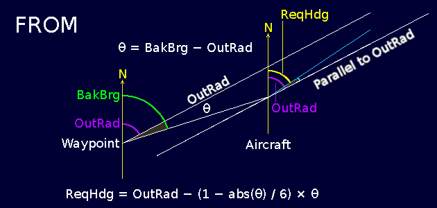
The 'FROM' phase of the program computes the required heading [ReqHdg] which the aircraft must fly in order to remain on — or make an asymptotic approach to — the waypoint's OUTbound radial. The formula for the FROM phase is quite different, being based on a non-linear heading correction factor to compensate for the inevitable decrease in accuracy with increasing distance from the waypoint.
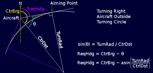
During the TURN phase, the idea is for the aircraft to follow the turning arc. If the aircraft is outside the turning arc, it is directed along the tangent to the arc that lies in the direction of the outbound radial. During this phase, the point of reference for the aircraft is the centre of the turning arc: not the waypoint itself. This means that the aircraft's point of reference is always about 10 km away, so distance and bearing measurements are always reliable, being free from the wild variations that can occur at close proximity.
Scan for [REF:TURN] in 'nav.c'.
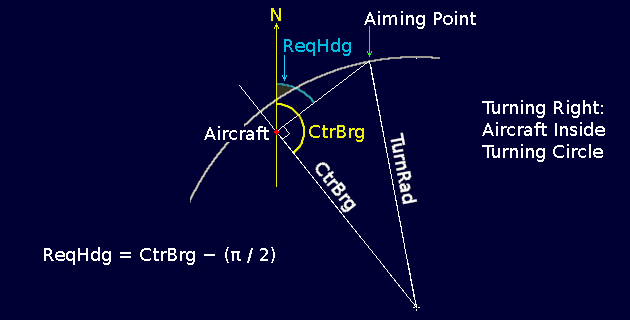
Under certain conditions, such as high winds, the aircraft can find itself inside the turning arc. In this case, the aircraft is directed along a heading at right-angles to the turning circle radius on which the aircraft currently lies. The required heading [ReqHdg] is simply the bearing of the centre of the turning circle [the aircraft's reference point] from the aircraft − π/2 [90°].
Note that the latitude and longitude of the centre of the turning arc are calculated for each of the waypoints in a route at route initialisation time in the program. Scan for [REF:TURNCTR] in 'nav.c'.
When the aircraft is beyond radio range of its current waypoint [assuming the waypoint is an active radio aid such as a VOR/DME station], it resorts to what I term 'trans-oceanic' mode. The aircraft obtains its current position [latitude/longitude] from a universally available source such as satellite-based global positioning systems [GPS, GLONASS, BeiDou, Galileo], an on-board inertial gyroscopic platform or a LORAN-style long-range hyperbolic radio-location system. Future systems could use natural phenomena such as pulsar signals, which would have the advantage of not being reliant upon sovereign or proprietary artificial infrastructures.
The trans-oceanic mode requires two waypoints. In the FROM case, where the aircraft is receding from its CURRENT waypoint, the second reference is the NEXT waypoint in the route. In the TO case, where the aircraft is approaching its CURRENT waypoint, the second reference is the PREVious waypoint. Scan for [REF: OCEANIC] in 'nav.c'.
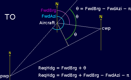
In the trans-oceanic FROM case, whenever the aircraft finds itself displaced laterally from the great circle that joins the current and next waypoints, it is steered such as to make an asymptotic approach back towards the great-circle. For this purpose, it is given a required heading according to the formula derived in the adjacent diagram. This uses the known bearings of each of the two waypoint from the point of view of the aircraft.
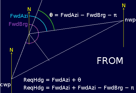
The trans-oceanic TO case is the same, in principle as the FROM case. However, the formula appears somewhat different because the variables, from which the two bearings are obtained, need to be computed in the reversed sense. The formulae in both cases are safe for any displacement on the globe. An extreme displacement, however, could cause the aircraft to back-track in order to re-join the correct great-circle path.
A complete air route thus comprises a series of straight lines between waypoints [which are, in fact terrestrial great circles] joined together by the turning arcs [which are circular sections] at the waypoints themselves.
Notwithstanding, this is not the track really followed by the aircraft. This is because there are two second order discontinuities in the path. One is where the inbound radial joins the turning circle. The other is where the turning circle joins the outbound radial. A real object with real inertia, like an aircraft, cannot be travelling a straight path and then instantaneously switch to follow a circular path. Its inertia will constrain it at best to do the following:
When joining the turning arc from the inbound radial, the aircraft cannot avoid overshooting the turning arc while it is in the process of changing from a straight path to a curved path. It will, ideally, follow a spiralated asymptotic tangent to the turning arc.
When joining the outbound radial from the turning arc, the aircraft cannot avoid undershooting the outbound radial while it is in the process of changing from a curved path to a straight path. It will, ideally, follow a sigmoidated asymptotic tangent to the outbound radial.
So why, in the interests of purity, did I not opt to construct the inter-waypoint paths as hyperbolic attractors? The answer is that neither hyperbolas nor any other conic section or combinations of conic sections fit the bill. For a start, unless all pairs of consecutive waypoints in a route are equidistant, the hyperbolic sections will be asymmetrical. That in itself would create a point of second order discontinuity at the point of closest approach to each waypoint. Secondly, if a left turn is followed by a right turn or vice versa, the hyperbolic sections would not meet at the half-way point between consecutive waypoints. They would be off-set sideways.
Notwithstanding, the imaginable smooth trajectory of a route of waypoints does exist in reality. For example, if we imagine the aircraft to be an electron projected on a path that causes it to have close encounters with a sequence of 'anti-protonic' waypoints, it should, as a result of the repulsive electrical force, follow this imaginable smooth trajectory. But the 'world line' that the electron would follow is not hyperbolic. Nor is it any derivable combination of hyperbolas, parabolas or ellipses — nor even precessing relativistic rosettes. We have encountered what is traditionally known as the Three-Body Problem. Where three or more bodies are involved in a system of attractive or repulsive force fields, the world-lines followed by the bodies are smooth and continuous; but mathematically underivable. They can be computed only by fine-grained iterative means, as done in this program.
Mathematics — specifically, in this case, algebraic geometry — is an artificial language by means of which we try, as best we can, to express our rudimentary understanding of how nature works. But our mathematics is definitely NOT the way nature actually does it. Nature works according to its own very different rules. It is becoming increasingly apparent that these rules operate at a very fine grain and that they are generally focused one time derivative higher than we think mathematically.
An example showing that our mathematics is not the way nature does things is in this very program. It is embedded in the program's most fundamental function: the Vincenty algorithm for computing distance and bearing. This works fine everywhere except near the North and South poles. There it goes haywire. Notwithstanding, the space around the poles is, in reality, no different from the space anywhere else on the planet. If we were to shift the polar origin of our coordinate system of latitude and longitude to Paris and its antipode, then trajectories across the Arctic Sea or central Antarctica would be completely free from navigational anomalies. Thus, it is our mathematics that is the problem: not the fundamental nature of a spherical [or more strictly ellipsoidal] surface.
Consequently, there is nothing impure about taking the systemically pragmatic option of using straight lines and turning arcs as the aircraft's 'world line' attractor through its route of waypoints. Making a simple 'best fit' and then applying error correction is the best option. In fact, this intuitively appears to be much closer to the way nature fundamentally operates.
6. Distance Travelled & Updated Position
The anticipated distance the aircraft travels during the current pass of the program is the newly computed command speed [CmdSpd] multiplied by the elapsed time [ET] since the last time through. The anticipated distance the aircraft is blown by the wind during the current pass of the program is the wind speed [WndSpd] multiplied by the elapsed time [ET] since the last time through. The wind speed may be as computed from live inputs of the aircraft's latitude and longitude, or an internally simulated wind, according to whether live input is switched on or off.
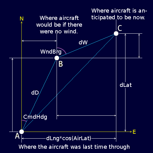
In the above diagram, A is the position [latitude and longitude] of the aircraft at the end of the previous pass of the program. B is the new position the aircraft would have exclusively due to engine thrust. C is the new position of the aircraft when the effect of wind is added vectorially to the effect of engine thrust. The unannotated blue line is the track followed by the aircraft as a result of the combined effects of engine thrust and wind. 'dLat' and 'dLng' are North and East components of the aircraft's displacement since the previous pass of the program. 'dLng' is multiplied by cos(AirLat) because longitudinal degrees represent that much shorter real distances than latitudinal degrees.
dLat and dLng are then respectively added to the previous latitude and longitude of the aircraft to get the new latitude and longitude of the aircraft.
7. Compute Required Height & Height Command
Scan for [REF:HEIGHT] in 'nav.c'. For the aircraft's passage between each pair of waypoints of the route, the updtHgt() function creates a sigmoidal path in the vertical plane beginning and ending respectively at points 100 metres above each of the 2 waypoints. This it does by referring to the standard monopolar sigmoid function shown below and then rescaling the height difference between the 2 waypoints and the distance between them. As shown, the function is for when the waypoint from which the aircraft is receding is lower than the waypoint it is approaching. For the converse case the sign of 'x' is reversed.
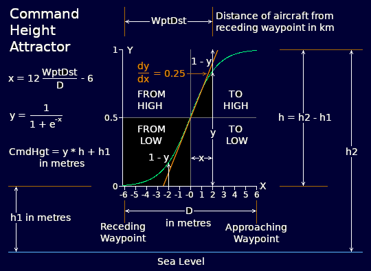
The updtHgt() function then attempts to move the aircraft, in the vertical plane, from its actual height, to merge asymptotically onto the height command sigmoid. This it does according to a simple iterative difference function. The aircraft height shown on the program's MAP tab is the command height to which the aircraft's autopilot or flight director must aspire.
This height control method lends itself well to stealth flight. Stealth flying, however, would require many more waypoints. In fact, every significant bump and pimple of the flight-track's terrain would have to be included in a route's sequence of waypoints. How low you can fly would be determined solely by how finely the route is waypointed. For covert stealth flights, the flight track's terrain profile would have to be carefully surveyed [probably from satellite photographs and radar imagery] and finely waypointed for every anticipated route in whatever part of the world.
The advantage of a finely graded waypoint route is that it can be flown silently. That is, it can be flown blind without having to use any active sensing devices such as ultrasonic or electromagnetic radar. Thus it can be flown in the dark without advertising the aircraft's presence to its surroundings.
Of course, obstacles to low flight may come and go. They can be temporary. In an adversarial situation, obstacles could be such things as strong nets spanning a valley. On-board sensory capability is therefore ultimately necessary. The first and most passive kind could be pitot pressure change sensors. Next could be visual or night-vision devices where the ambient conditions supply adequate illumination. But passive devices may have to trigger short bursts of active sensor operation where necessary. To minimise the risk of detection, these bursts would have to be kept as short as possible.
Aircraft Data & Map Display
The aircraft's position and data are updated by each pass of updtTrack() throughout a flight. This occurs every 5, 2 or 1 seconds, 500, 200 or 100 milliseconds according to the item selected in the Refresh Rate menu in Tab 2. Consequently, the visual display of the aircraft's flight data and map position must be re-displayed. This re-displaying is done by the function T0updt() at every pass of the clock loop in main(). However, T0updt() is also called after the default route has been initialised after the program is first started and also every time a new route is selected or a flight is reset.
The first action of T0updt() is to actualise the flight data figures on the left of the window. It then proceeds to update the map display. To do this, it scans through all the geographic features [including waypoints] in the currently selected route. For each geographic feature, it calls the Vincenty Inverse function to obtain its distance from the aircraft. The aircraft is always at the map centre. If the feature is within visible map range, it is shortlisted for display. Each geographic feature on the shortlist is then drawn and named in its appropriate position on the map.
Please note that in this C version of the program, unlike the Java version, non-English place names cannot contain accented letters. It is possible to include the extended font libraries but they were excluded to save space.
Once all the in-range geographic features have been drawn and named, the inbound and outbound radials plus the turning circle arc are drawn for the particular waypoint that is currently being referenced by the aircraft.
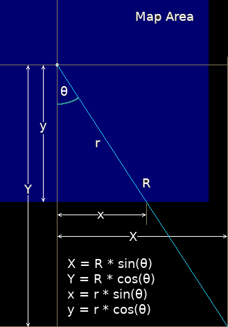 The C version of the program is so fast that it is not necessary to buffer the map graphics. However, the absence of graphics buffering makes it necessary to chop off any drawn object that would otherwise violate the boundary of the map area. The only offenders in this regard are the inbound and outbound radials of the current waypoint. The geometry for chopping these radials short of the map boundary is shown in the adjacent diagram. The chopping must be done separately for each of the inbound and outbound radials. Although the geometry is fairly simple, the coding required to implement it is unintuitively long.
If the aircraft is beyond radio range of its referenced waypoint, it is navigating in trans-oceanic mode. For this, instead of the inbound and outbound radials plus turning arc, the display shows a pair of yellow guide bars that point respectively towards the next and previous waypoints between which the aircraft is flying.
Do a word scan for [REF:CHOP1] and [REF:CHOP2] in 'nav.c'.
Finally, the cross-hairs at the centre of the map [representing the position of the aircraft] and the little compass at the bottom right of the map area are displayed.
Note that the sequence in which the components of the map are displayed ensures that they are layered on the map area in the correct order: the geographic features being the bottom layer over which are displayed the radials and turning arc [or trans-oceanic guide bars] over which are displayed the cross-hairs and compass.
A Philosophical Point
You may notice that on the moving map, as the aircraft advances along its track, the various waypoints and features in view tend to move relative to each other. For example, when the aircraft first starts to turn onto track, Brighton, Guildford and Oxford seem to move relative to each other in independent small jerks. This would appear to be absurd. We all know that, in "reality", these cities stay in fixed positions relative to each other.
This is, of course, an effect that is entirely due to the limitations of the pixel raster of the map area. If the pixels were infinitely small then all would move together smoothly with the cities maintaining their fixed geographic relationships as they moved relative to the aircraft. Notwithstanding, even with infinitely small pixels, the stability of the relative positions of the cities would be limited by the precision of the floating point double arithmetic within the program. Thus, theoretically, they would still appear to suffer the absurdity of relative motion. Consequently, from the point of view of the aircraft (and the sensing devices on board) there will always appear to be at least some degree of relative motion between different supposedly fixed objects.
This gives rise to a universal corollary. An observer can only perceive reality from his own point of view in space and time. So an observer's view of anything in the universe is necessarily limited by the capabilities of his senses, his powers of perception and the way in which the intervening space and its content may warp or disperse the light passing through it. Consequently, where he sees a distant object may not be where it "really" is.
Observation and perception is ultimately limited by the speed and trajectory of the light emitted by the object, by which the observer observes it. However, where the object appears to be is also the position from which the object affects the observer gravitationally and in every other possible way. Consequently, within an observer's view of the universe, that is where the object "really" is.
On the universal scale, therefore, the relative motion of objects, which are supposedly always at a fixed distance from each other, from the observer's point of view as seen on the navigation map is not quite so absurd as it would at first appear. In an observer's universe or event-horizon, where things appear to be is where — to him — they really are.
All the routes currently on file are listed here. There is one line of information for each route. The routes are numbered from zero upwards. The route number is the first item on each line. This is followed by two 3-digit numbers. These are respectively the primary runway headings of the airport at which the route begins and of the airport at which it terminates. This is followed by the route name, which comprises the names of the origin and destination airports. Provision is made within the software for up to 100 routes, although this can be extended.
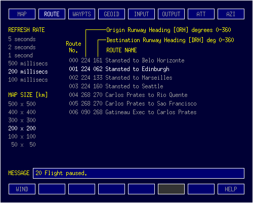
If there are more than 12 routes on file, a scroll bar appears on the right of the list so that all route entries may be seen by scrolling the list using the mouse wheel. A route is selected by clicking on its name. The selected route [the one that the aircraft will fly when the GO button is pressed on the MAP tab] is highlighted in bright white.
On the left of this tab are two selector menus. The upper one allows you to select the refresh period of the map. That is, how often the position of the aircraft relative to all the visible geographic features [including waypoints] is re-computed. For transoceanic legs [between one waypoint and the next] a 5-second update period is more than adequate. For short-haul and approach manoeuvres, a half-second [500 millisecond] update period is appropriate. A 100 millisecond update period is only required when the ATAV function is in use. [The ATAV function is not included in this demonstration version of the program.] The lower selector menu allows you to select the map scale for the MAP tab. In general, the 200 x 200 kilometre map is ideal. For approach in tight corridors, the 50 x 50 kilometre scale is useful. The 500 x 500 kilometre scale is ideal for waiting for first sight of your landfall waypoint after a long transoceanic leg.
The message line is where the program displays messages regarding the state of a flight and warning/error conditions. Advisory messages are displayed in green, cautionary messages in yellow and error conditions in red.
The WIND button [bottom left] enables a simulated wind to act upon the aircraft during flight. Only a single value is available. This facility could be augmented by implementing real-time access to a global wind model, which would return wind speed and direction when given the aircraft's current position and height.
This tab contains a list of the waypoints that make up the currently selected route. A list comprising more than 16 waypoints may be scrolled using the mouse wheel. Like routes, the waypoints within a route are numbered, starting with zero. Each line of the list contains the details of 1 waypoint. Geographic features that aren't waypoints are excluded from this list. The waypoint's name is limited to 20 characters. The waypoint's latitude & longitude in degrees:minutes:seconds are then shown, followed by its elevation above sea level in metres.
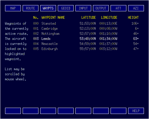
Clicking on a waypoint line causes it to become highlighted in bright white. This action repositions the aircraft to the highlighted waypoint, as can be seen by switching back to the MAP tab. The software currently provides for up to 50 waypoints in any given route, although this can be extended if required.
An addition at the lower left of the WAYPTS tab is a display of the maximum number of iterations that were necessary for the Vincenty computations to converge, as recorded during the current program session. A separate maximum count is shown for both the Direct Geodetic and the Inverse Geodetic computations.
The Earth is almost spherical, but not quite. At sea level, its equatorial radius is 6378137 metres; its polar radius is 6356752 metres — a difference of only 21385 metres. Earth's sea level radius may thus be written as 6367445 ±10693 metres: that's only ± 1·21 times the height of Mount Everest. Thus, its deviation from being perfectly spherical is very small. But, for accurate navigation on a global scale, it is necessary to take account of this deviation. The Vincenty method, used by this program to calculate distance and bearing thus treats the Earth as an ellipsoid.
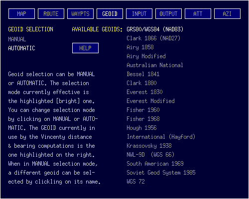
Notwithstanding, though it be a slightly flattened sphere, the Earth is not a perfect oblate ellipsoid. This is because the distribution of materials of different densities that make up the planet is far from homogeneous. This causes variations in gravitational effects. As a result, the Earth is pear-shaped. The bottom of the pear is at the South Pole and the neck of the pear is at the North Pole. Consequently, the mean ellipsoid of the Earth does not fit equally well — or even adequately — in all parts of its surface.
Over the past century and a half, therefore, various navigators and mathematicians have calculated separate ellipsoidal models [called geoids] that fit well for specific regions of the globe. The most notable and established of these are the 18 listed on the left of this tab. It is up to you to research and select the one that best suits the routes you fly.
When the selector on the left is set to MANUAL, you may click on the name of the geoid you wish the Vincenty distance and bearing function to use. When you do so, it will become highlighted in bright white as the geoid currently in effect. When AUTOMATIC is selected, the program uses the current latitude and longitude of the aircraft to select automatically the best geoid to use. The selection mechanism is, however, quite rudimentary in the present implementation. Perhaps I shall improve it in the future.
Most of this tab is occupied by a square dark blue map panel. The aircraft is represented by a cross at the centre of the map panel. The front of the aircraft always faces exactly in the upward vertical direction on the map panel. The map displays named geographic features that are currently within map range of the aircraft. Some, but by no means all, of these geographic features are designated waypoints that mark the route the aircraft is flying. All visible geographic features move downwards as the aircraft proceeds along its route, while the aircraft remains 'stationary' at the map's central cross. The small compass annunciator at the bottom right of the map indicates 'North' relative to the direction in which the aircraft is pointing.
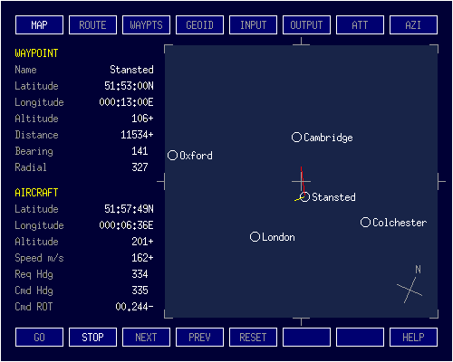
The items displayed on the left of the tab area show the current values of the navigational parameters. The items in the lower part show the position, height, speed, headings and turn rate of the aircraft. Those above show the position, height, distance, bearing and selected radial of approach or recession pertaining to the waypoint to which the aircraft is currently 'locked on'.
Across the bottom of the tab is a set of 8 control buttons, which may be actioned by clicking on them with the mouse. Separate GO and STOP buttons operate in mutual exclusion. That is, if the flight is in progress, clicking on the STOP button stops the flight but otherwise does nothing. Similarly, if the flight is stopped, or has not yet been started, clicking the GO button starts the flight. Otherwise it does nothing. Clicking the NEXT or PREV buttons respectively stop the flight if it is in progress and move the aircraft to the next or previous waypoint in the route. The RESET button stops the flight and sets the aircraft back to the beginning of the route. The SCALE+ [zoom-in] and SCALE- [zoom-out] buttons re-scale the map to cover a smaller area and larger area respectively. The HELP button opens this Web-based narrative.
NOTE: real flights along the sample routes provided in this demo, especially intercontinental flights, take a long time. To reduce flight time, I have used a fictitious aircraft with a top speed of 1000 metres/second [m/s]. Mach 1 = 343 m/s. The aircraft does however slow down for the turn at each waypoint and its take off and landing speed is a mere 75 m/s.
| Comparisons | m/s | km/h | mph | knots
|
|---|
| Top Speed of Fictitious Aircraft | 1000 | 3600 | 2237 | 1944
|
| Its Take-off and Landing Speed | 75 | 270 | 168 | 146
|
| cf: Dreamliner Cruising Speed | 254 | 913 | 567 | 493
|
| cf: Speed of Sound [Mach 1] | 343 | 1235 | 767 | 667
|
The shorter light blue horizontal line in the illustration shows the current pitch of the aircraft. Being below the horizontal grey graticule line indicates that the aircraft is slightly nose-up. The shorter horizontal yellow line represents the current pitch command. It is above the blue line, so it is currently commanding that the aircraft's node be brought down slightly. The full vertical scale of the indicator is ± 30°. Both the short bars move in the vertical sense only and always remain horizontal with respect to the graticule.
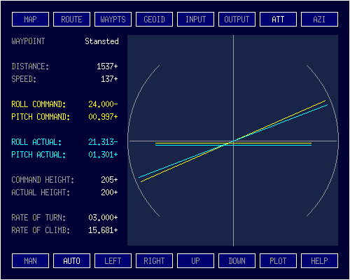
The longer blue bar indicates the current roll angle of the aircraft. In the illustration, it is showing that the aircraft is rolled [or banked] to the right [the right wing is lower than the left wing]. It is important to realise the sense of the indication. You, the observer, are on the aircraft. You are sitting in the pilot's seat and therefore you — along with the grey cross of the attitude indicator you are looking at — are not vertical but are tilted to the right. The light blue line is therefore at the angle of the horizon with respect to you.
The corresponding yellow bar indicates the current value of the roll command. In the illustration, it is telling you that the aircraft needs to be rolled further to the right in order to follow its prescribed track. The two arcs are there simply to indicate a 45° roll. The roll command bar turns red for roll angles in excess of 60° and the indicator will not go beyond 86°.
The first two buttons at the bottom left of the tab are the MAN and AUTO buttons. In MANual mode, only the yellow pitch and roll command bars driven by the Global Navigator program are shown. The default mode is AUTO. In this mode, the two blue bars indicating a simulated pitch and roll response of the aircraft are shown also. The LEFT and RIGHT buttons inch the roll angle indication to the left and right respectively. The UP and DOWN buttons inch the pitch angle up and down respectively. These are to verify that the indicator is working properly. These 4 buttons are disabled while a flight is in progress.
The self-evident information in the narrower panel on the left of the tab gives a more accurate digital representation of the aircraft's commanded and actual pitch and roll, plus other useful support data.
Clicking on the PLOT button causes the content of the ATTitude tab to be replaced with a graph. This graph is merely for verifying that the program's height profiling function is working correctly. For this reason, it only covers a 0 to 300 metre height range. It indicates the height profile followed by the aircraft between waypoints. It is important to verify that this follows the expected smooth sigmoidal path from one waypoint to the next and from the first waypoint's height + cruising height to the next waypoint's height + cruising height.
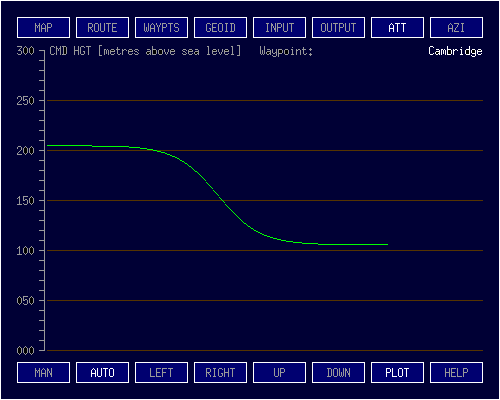
On the final leg of a flight, the aircraft remains at the height + cruising height above the final waypoint and follows a much steeper sigmoidal path from the point at which it must begin descent all the way to the touchdown point. The distance from touchdown at which the sigmoidal descent path must begin is computed such that the maximum slope of the sigmoidal path is 3° [standard glide slope angle].
The Azimuth Tab, is as shown in the adjacent illustration. The fixed grey circle and cross lines represent the horizontal orientation of the aircraft. The front of the aircraft is at top centre. The green 4-point compass forms an Earth reference for the aircraft's orientation at any instant. The light blue bar shows the direction in which the aircraft is currently required to fly. The yellow bar shows the direction in which the aircraft is currently being commanded to fly. This is a damped version of the required direction to avoid change of direction commands becoming too extreme.
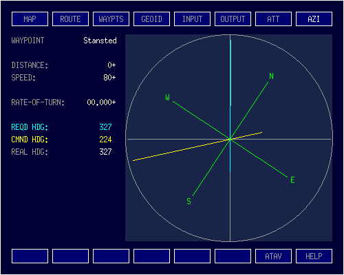
The information conveyed in analogue form by the grey circle and cross, the compass plus the blue and yellow bars is shown digitally on the left of the Tab. The identity of the current waypoint, the waypoint's current distance plus the aircraft's current speed and rate of turn are also shown as supporting information.
During a typical turn, the command heading gradually moves towards the required heading, to which the aircraft endeavours to align. When a turn operation has finished, both the blue required heading bar and the yellow heading command bar will align with the top vertical grey cross bar. The green compass bar will then indicate the aircraft's coincident required, commanded and actual headings.
The penultimate button at the bottom of the AZImuth Tab is labelled ATAV. This demonstration version of Global Navigator II does not include ATAV [attack avoidance] functionality.
ATAV is based on an inverse of the starling murmuration algorithm, in which the 'starlings' [enemy interceptors] are the predators and the interloper [the aircraft] is the prey. The flight control functions employ an augmented inverse murmuration algorithm to escape an orchestrated attack by the 'starlings'.
ATAV can be activated manually or programmed to activate automatically in response to the trajectorial behaviour of other flying objects within the aircraft's murmuration vicinity.
ATAV manoeuvres are superimposed, as and when necessary, upon the aircraft's nominal flight path along its current route. In this demonstration version of Global Navigator II, this button is simply left in place for completeness.
The input tab monitors the input stream of regular real-world position and height updates from external equipment such as a GPS receiver, an inertial platform or reactive radar. The data is displayed as successive lines, each containing the aircraft's current latitude and longitude [in radians] and its height [in metres]. This data is passed to Global Navigator II via stdin, piped from an auxiliary program that reads data from the external hardware. The auxiliary program could read it in from a USB port or a bus-based expansion card.
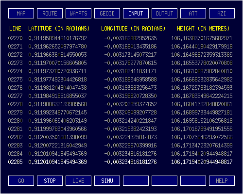
The default is no external input, with Global Navigator II generating the aircraft's position and height input stream from its internal SIMUlated terrestrial environment. Clicking the LIVE button to receive live input from stdin will cause the LIVE button to illuminate in RED, indicating that LIVE input is not implemented in this demonstration version of Global Navigator II. SIMUlated input remains in effect.
During a flight, the output tab displays the flight direction commands emitted by Global Navigator II. By default, these commands go nowhere. However, clicking on the STDOUT button, causes the program to send these commands to stdout. From here they can be piped to another auxiliary program that sends them on to a real-world autopilot or flight director. Clicking on the FILE button will cause the program to send the commands to a file named 'output.txt', which could be configured as a device driver for an external autopilot or flight director.
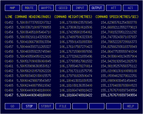
For convenience, the GO and STOP buttons appear on this tab so that the current flight can be paused and re-started from here.
© March 2020, 01 Sept 2020 Robert John Morton


 A waypoint encounter comprises three phases: a 'TO' phase, a 'TURN' phase and a 'FROM' phase. The example on the left shows the aircraft's encounter with the Montreal waypoint. The previous waypoint in the route is Hawkesbury. The next waypoint is Sorel-Tracy. The 'TO' phase of the Montreal encounter is from the half-way point between Hawkesbury and Montreal up to the point where the inbound radial touches the Montreal turning arc. The 'FROM' phase is from where the outbound radial touches the Montreal turning arc to the half-way point between Montreal and Sorel-Tracy.


 The C version of the program is so fast that it is not necessary to buffer the map graphics. However, the absence of graphics buffering makes it necessary to chop off any drawn object that would otherwise violate the boundary of the map area. The only offenders in this regard are the inbound and outbound radials of the current waypoint. The geometry for chopping these radials short of the map boundary is shown in the adjacent diagram. The chopping must be done separately for each of the inbound and outbound radials. Although the geometry is fairly simple, the coding required to implement it is unintuitively long.


