Contents
The software data structure containing information about the aircraft which relates to its navigation.
The software structure and simulation of the aircraft's terrestrial radio environment.
Computing the signal strength of a given station at the aircraft. This includes:
The mathematical simulation of the antenna radiation lobes of various types of navigational aid.
Simulation of the Morse code call sign keying of the radio navigational aids which are currently being received by the aircraft's receivers.
Simulation of the tuning characteristics of the aircraft's continuously tunable LF/MF ADF receivers.
Types of aircraft navigation receivers plus software data structures and procedures to simulate their operation.
Using LF/MF and VHF radio navigation stations as air route way points including the mathematics of course intercepts and the functions which simulate them.
Simulation of the aircraft's linear and rotational position and motion and also its on-board attitude reference systems.
Simulation of the runway landing task and the Instrument Landing System.
Overview and integration of the simulation software.
A collection of navigation functions written in 'C' relating to the simulation of aircraft navigation equipments and their terrestrial environments.
Details of the aircraft's position is maintained by the flight program in a structure:
struct AirData {
  double
    Lat,    // aircraft's latitude
    Lng,    // aircraft's longitude
    Ht,     // height above sea-level (Earth Radians)
    GndHt,  // estimated height of ground beneath aircraft
    Hdg,    // ground-track heading (compass + wind − drift angle)
    Des,    // aircraft's angle of descent
    Spd,    // aircraft's true horizontal ground speed
    Pitch,  // aircraft's pitch angle
    Roll,   // aircraft's roll angle
    Rot,    // rate-of-turn in radians per second
    TD;     // diameter of aircraft's minimum turning circle
  int Sw;   // Id of NAV receiver switched to navigation computer
} Air;
Details of all radio navigation stations are entered into and kept in a Ground Station Data Source file GSS.DAT. A compact ground station data file GS.DAT is then generated from GSS.DAT by the Ground Station Data compiler.

The record for each station within GS.DAT has the following structure:
struct StnData {
  char    Type;       // NDB,RRG,VOR,ILS,DME,AMK,BMK,OMK,MMK,IMK
  double  Lat,        // Latitude
          Lng,        // Longitude
          Ht,         // Ht of stn above sea level (Earth radians)
          Rng,        // Effective Range
          Hdg;        // Runway or airway heading
  int     RadPat;     // 0=omni,1=RRG,2=Marker lobe,3=ILS lobe
  long    Frq;        // Frequency
  char CallSign[16];  // call sign coding string
  time_t  TimeOut,    // Time before next dist & bearing check
          OldTime;    // Time when dist & bearing last checked
  BOOL Receivable;    // Flag saying if station is in range
} Stn;
The first 9 items are constants for a given station, the last 3 vary with aircraft position. GS.DAT is generated from a ground station data source file GSS.DAT into which details of each ground station are typed initially.
Active Stations List
For a station to be active during simulation, its details have to be in memory. So we need to copy the details of any station which is in (or about to come into) range of the aircraft into a data structure in memory. Conversely, to conserve memory, we must delete stations from memory when they go more than a certain amount out of range of the aircraft.

So that we can refer to an active station's data easily, we make the active stations list comprise an array of pointers, each element of which contains a pointer which points to a station's data structure as follows:

Station data is kept in a structure of type TxData. Tx is the name of the array so the pointer-constant, Tx points to the first element of the array. NumTx is the maximum number of elements in the array, ie the maximum number of stations we can accommodate concurrently. TX points to the last element + 1 of the array. TxHi points to the highest currently occupied element. tx points to the element containing the pointer to the data pertaining to the station which the program is currently dealing with.
The TxData Structure
The data structure for each currently-active station has the following contents.
struct TxData {        // DATA STRUCTURE FOR AN ACTIVE GROUND STN
  int StnNum,          // Stn's record No within GS.DAT file
      StnType;         // see below
  double Lat,          // Latitude
         Lng,          // Longitude
         Ht,           // Ht of stn > sea level in Earth radians
         Rng,          // Effective Range
         Hdg,          // Runway or airway heading
         Len,          // Runway length (for ILS only)
         GS;           // Glide Slope Angle (for ILS only)
  int  RadPat;         // 0=omni, 1=RRG, 2=Marker lobe, 3=ILS lobe
  long Frq;            // Frequency
  char CallSign[16];   // call sign coding string
  BOOL Single;         // morse version of callsign in Morse[]

  double Dst, PrevDst, // Current & previous dist from aircraft
         Brg,          // Current true bearing from aircraft
         Sig;          // Signal strength of tx at aircraft
  char *pCallSign,     // ptr to current posn in callsign string
       Morse[48],      // Morse sequence in timer durations
       *pMorse;        // points to current Morse element
  int Repeat,          // Nº of morse seq repeats still to do
      Pitch,           // audio freq of morse tone (see below)
      MorseTimer;      // duration of current Morse Code element
  BOOL MorseKey;       // current state of Morse Key
}
*Tx[NumTx],            // ptrs to NumTx active stn structures
*(*TxHi);              // ptr to Tx[highest occupied element+1]

StnType   1 = NDB, 2 = RRG, 3 = VOR, 4 = VOR/DME,
          5 = ILS, 6 = ILS/DME, 7 = DME, 8 = AMK,
          9 = BMK, 10 = OMK, 11 = MMK, 12 = IMK

Pitch     0 = 1020Hz, 1 = 1300Hz, 2 = 3000Hz
The items above the blank line are fixed items copied from the GS.DAT file. The items below the blank line are updated by the real-time NAV software.
SetUpTxData()
When a station comes within receivable range, this function copies its details into a newly-allocated TxData structure. Apart from simply copying the fixed data items from the appropriate GS.DAT disk record, SetUpTxData() also possibly sets up the station's callsign for keying. If a station has a simple callsign sequence (ie only one semi-colon appears in it - see later in the section on callsign keying), SetUpTxData() calls SetUpCallSign() which translates the callsign sequence into Morse code once for the whole time the station is active. If the station has a multiple callsign (ie more than one semi-colon appears in it) then each segment of the callsign is set up dynamically during the on-going callsign keying cycle.
void SetUpTxData(struct TxData *t) {
  char *u = Stn.CallSign,  // ptr to callsign data in disk stream
       *v = t->CallSign;   // ptr to callsign in TxData structure
  t->Type = Stn.Type;      // Type of Station
  t->Lat = Stn.Lat;        // Its Latitude
  t->Lng = Stn.Lng;        // Its Longitude
  t->Ht = Stn.Ht;          // Its height > sea level (Earth rads)
  t->Rng = Stn.Rng - RNG;  // True transmission range
  t->Hdg = Stn.Hdg;        // runway or airway heading
  t->RadPat = Stn.RadPat;  // antenna radiation pattern or gain
  t->Frq = Stn.Frq;        // Frequency
  if(*u++ = 'S')           // S = single, M = multiple callsign
    t->Single = TRUE;      // single callsign
  else t->Single = FALSE;  // multiple callsign
  for(;*u > '\0';u++,v++)  // copy all but S/M byte of callsign in
    *v = *u;               // to TxData callsign buffer CallSign[]
  *v = '\0';               // and terminate it with a null char
  t->pCallSign = Stn.CallSign;  // set ptr to start of callsign
  t->MorseKey = TRUE;      // for first Morse element
  t->pMorse = t->Morse;    // set ptr to start of Morse Code
  if(t->Single == TRUE)    // if it is a single-part callsign
    SetUpCallSign(t);      // translate it to Morse once-only here
}
Stations are added to and deleted from the active stations list by the function:
BOOL SetStn(int StnNum,   // Stn's Record Nº in GS.DAT file
            BOOL flag) {  // TRUE if new stn just come in range

  #define RNG 0.0157079632675  // 100km in Great Circle radians
  BOOL result = FALSE;
  static struct TxData
    *(*TX) = Tx + NumTx,  // ptr to last element in ptr array
    *t,                   // ptr to subject Tx Data structure
    **tx;                 // ptr to ptr to Tx Data structure

  if(flag == TRUE) {      // IF A STATION HAS JUST COME INTO RANGE

    for(tx = Tx;tx < TX;tx++) {  // find spare slot in ptr array
      if(*tx == NULL) {          // then allocate memory for station data
        *tx = (struct TxData *)malloc(size_t sizeof(struct TxData));
        if(*tx != NULL)
          result = TRUE;
        break;
      }
    }
    if(result == TRUE) {  // if enough memory could be allocated
      if(TxHi < tx)       // keep track of the
        TxHi = tx;        // highest used element
      SetUpTxData(*tx);}  // copy stn data to TxData structure

  } else {                // ELSE A STATION HAS JUST GONE OUT OF RANGE

    for (tx = Tx;tx < TX;tx++) {  // find its Tx Data
      if((*tx)->StnNum == StnNum) {
        free(*tx);        // free the memory used by this station
        *tx = NULL;       // clear ptr in TxData ptr array
        if(TxHi == tx)    // keep track of the
          TxHi--;         // highest used element
        result = TRUE;
        break;
      }
    }
  }
  return(result);
}
Rough Distance Check
When the simulation program is first started up, part of the initialisation process must be to calculate accurately and fully the distances of all ground stations relative to the aircraft's starting position. This must also be done whenever the aircraft is artificially repositioned by the flight simulation instructor.
From then on, however, the distance of each station from the aircraft must be recalculated regularly to see if an out-of-range station has moved into range or an in-range station has moved out of range. Calculation of distance by spherical geometry is time-consuming. So we must find a method of checking stations which resorts to recalculating their distances fully only when it absolutely has to.
If the aircraft has a maximum speed VMAX and the last calculated distance to a given station is 'd' and the effective transmitting range of the station is Stn.Rng, then the aircraft cannot possibly get into range of the station within a time less than (d - Stn.Rng)/VMAX no matter what direction the aircraft is travelling in. This formula provides a quick means of checking when we need to re-compute the station's true distance from the aircraft. This principle may be visualised as follows. Whenever a station's true distance is recalculated, the station emits a ghost which travels towards the aircraft at a constant speed VMAX irrespective of the aircraft's own speed or heading:

It is not necessary to re-calculate the station's distance until a time Stn.TimeOut has elapsed. The ghost behaves a bit like a photon which will move towards an observer at the speed of light 'c' irrespective of the relative speed of the Earth and the observed star which emitted it. We therefore cycle through the GS.DAT file continually decrementing each station's Stn.TimeOut each pass by the amount of time that has elapsed since the previous time we checked that station.
Great-Circle Distance

When a station's Stn.TimeOut expires we call the function GetDst() to compute its true accurate great-circle distance as follows:
double GetDst() {               // COMPUTE THE DISTANCE OF AN
  #define Pi 3.1415926535       // OBSERVED FROM THE OBSERVER
  double
    dlong = Stn.Lng - Air.Lng,  // Longitudinal difference
    SinAirLat = sin(Air.Lat),   // Sine of latitude of observer
    CosAirLat = cos(Air.Lat),   // Cosine latitude of observer
    SinStnLat = sin(Stn.Lat),   // Sine of latitude of observed
    CosStnLat = cos(Stn.Lat);   // Cosine latitude of observed
  if(dlong >  Pi) dlong -= Pi;  // change the range of dlong
  if(dlong < -Pi) dlong += Pi;  // from 0 - 2p to -p - +p
  CosDst = CosAirLat * CosStnLat * cos(dlong)
         + SinAirLat * SinStnLat;
  if(CosDst > +1) CosDst = +1;  // avoid acos() domain errors
  if(CosDst < -1) CosDst = -1;
  return(acos(CosDst));         // return distance in radians
}
If as a result, the station is now found to be in range of the aircraft, its details are copied into a TxData structure if it is not already in one. If as a result, the station is now out of range of the aircraft, its TxData structure is deleted if it exists.
NOTE: Simple spherical geometry is used in the above function. The Vincenty iterative ellipsoidal methods for computing accurate distance and bearing had not been invented at the time the software described herein was originated.
Distance-Checking Cycle
The following 'C' function determines whether or not a ground station is currently receivable at the aircraft. It is called about every 200 milliseconds.
void StnPoll() {
  #define VMAX 0.4363323129861111E-4  // 1000km/hr in radians/sec
  static int StnNum = 0;     // Station No preserved from prev pass
  double d;                  // distance of station from aircraft
  if (StnNum == NumStn)      // Station's record number in the
    StnNum = 0;              // Ground Station Data file GS.DAT
  GetStn(++StnNum);          // get data of next stn in GS.DAT file
  if (Stn.TimeOut > 0) {     // if not yet time to recalculate distance

    /* Decrement the station's distance re-calculation timeout,
    and advance the station's ghost towards the aircraft. */
    Stn.TimeOut -= SysTime - Stn.OldTime; Stn.OldTime = SysTime;

  } else {  // Else station's ghost is now in range of aircraft, so...

    /* If aircraft is within station's signal range, and station
    is not currently on the 'receivable stations' list then.. */

    if(((d = GetDst()) < Stn.Rng) && (Stn.Receivable == FALSE)) {

      /*Attempt to put the station on the 'receivable' list and
      if successful store its updated status to the GS.DAT file*/

      if((Stn.Receivable = SetStn(StnNum, TRUE)) == TRUE)
        PutStn(StnNum);

    } else {  // Else the station is out of receivable range, so...

      /* If station currently on 'receivable' list, delete it
      from 'active stations' list and set it as unreceivable. */

      if (Stn.Receivable == TRUE) {
        SetStn(StnNum, FALSE);
        Stn.Receivable = FALSE;
      }
      /* Set the timeout to next distance check and then
      store the updated station data to the GS.DAT file. */
      Stn.TimeOut = (d - Stn.Rng) / VMAX; PutStn(StnNum);
    }
  }
}
Stn.Rng as given in GS.DAT is actually 100km more than the maximum range at which the station can be received. This gives StationPolling() time to get the station on to the active list since an aircraft doing 1000km/hr can get 100km closer to a station in less time it takes to check 2,000 stations at 200ms per station.
The signal strength, as delivered by a radio-navigation station at a given aircraft position, depends on its transmitter power, its radiation pattern and line-of-sight criteria.
The signal strength, as delivered by a radio-navigation station at a given aircraft position, depends on:
- transmitter power (expressed as station's maximum effective range)
- radiation pattern (a function of the aircraft's bearing from the station)
- line-of-sight criteria (affects VHF stations only)
Omni-directional stations such as non-directional beacons [NDBs] and VHF omni-directional range stations [VORs] radiate equal signal power in all horizontal directions. Their radiation patterns are therefore shown as circles:

The following function computes the signal strength for any station (such as a VOR or an NDB) with an omni-directional radiation pattern, ie one which radiates with equal strength in all horizontal directions.
double OmniSignal( struct TxData *t ) {
  return((t->Rng - t->Dst) / t->Rng);
}
A radio range station [RRG] radiates in 4 broad horizontal lobes as follows:

The following function uses the current bearing of the aircraft from the radio range station to determine whether the aircraft is in one of the station's 'A' quadrants or in one of its 'N' quadrants. It then places an 'A' or an 'N' respectively in the 4th character position of the first segment of the station's callsign so that the function CallSignKeying() will key an 'A' or an 'N' as appropriate.
The function returns the directional attenuation factor of the station's signal computed according to a radio range station's 4-leaf clover radiation pattern given by the formula: Signal = MaxSignal * sin( 2 * Bearing ).
double RadioRange( struct TxData *t ) {
  #define Pi 3.1415926535
  #define HalfPi 1.5707963267
  char s;             // contains 'A' or 'N' according to quadrant
  double b = t->Brg;  // bearing of aircraft from station
  if(b > Pi)          // if aircraft in 3rd or 4th quadrants,
    b -= Pi;          // consider it in the first or second
  if(b > HalfPi)      // if aircraft in the second or 4th quadrants
    s = 'N';          // key the letter 'N'
  else                // if aircraft in the first or 3rd quadrants
    s = 'A';          // key the letter 'A'
  // Put letter in 4th character position of first callsign segment
  *( t->CallSign + 3 ) = s;
  // Compute directional reduction in station's effective range
  double a = t->Rng * sin( b + b );
  // return the current signal strength of station at aircraft
  return( ( a - t->Dst ) / a );
}
Radio marker beacons are placed at strategic points along airways (airways markers) and at approaches to airport runways (landing markers). Landing markers are only effective up to 8,000 feet. A Marker's horizontal radiation pattern is elliptical with the minor axis of the ellipse in line with the airway or the runway's extended centre-line as shown below for a typical runway approach.

Markers operate on a single fixed radio frequency. Airways markers transmit a call sign in slow morse code. Landing markers transmit slow morse signals as shown above. To simulate a marker beacon we must first calculate its signal strength at the aircraft. The signal strength at the aircraft's marker receiver depends on the aircraft's height, distance and relative bearing from the marker, the marker's transmitter power and the radiation pattern of the marker's antenna. The power and radiation pattern of the marker are constants, so we can say that:
Signal strength, S = F(h, d, F)
In detail, the signal strength at the aircraft is calculated as follows:

Having found a we can work with a side view of the marker's vertical radiation lobe as shown below rather than at the odd relative bearing angle. The lobe (which has an elliptical horizontal cross-section) is a surface over which the signal is a constant strength. An approximate formula for the vertical cross-section is:

The following QuickBASIC program generates the above lobe. It also produces two small side-lobes at the bottom which are rather true to life. Note that the formula used for this simulation bears no resemblance to the mechanism which produces real antenna radiation patterns.
screen 9                  'switch to EGA enhanced mode graphics
window(-50,-20)-(+50,+80) 'move window origin to lower centre
XYscaler = 4/5            'PC screen X scaling is 4/5 its Y
Pi = 3.1415926535 : A = Pi / 2
Rmax = 60                 'simulates signal strength
n = 3.5                   'simulates antenna gain
for theta = -A to +A step .0005
x = cos(3.5 * theta) * cos(theta)   'lobe profile formula
if x => 0 then
  R = Rmax * sqr(x)
  a = R * sin(theta)         'distance component along airway x
  h = R * cos(theta)         'height y
  pset(a * XYscaler, h), 15  'plot the point
end if
next : end
The following function computes the signal strength within the field of a high-gain antenna as used by a marker beacon or an ILS station. The square root expression is the distance 'R' along the central axis of the station's radiation lobe at which the signal is the same strength as it is at the aircraft.
double RadiationLobe (
  double rsq,    //square of distance between aircraft and station
  double R,      //maximum effective range of station
  double theta;  //relative bearing between aircraft and lobe axis
) {
  return((R - sqrt(rsq /(cos(3.5 * theta) * cos(theta))))/ R);
}
The function below finds a marker's signal strength at the aircraft. The range of a marker beacon is given as a vertical range or height. This is because a marker's radiation lobe points upwards rather than horizontally like a Radio Range or ILS. The function finds the signal strength at the aircraft by finding the height on the central vertical axis of the marker's radiation lobe at which the signal is the same strength as at the aircraft. It then compares this with the maximum range of the marker (vertically) to find the relative signal strength at the aircraft.
double MarkerBeacon( struct TxData *t ) {
  double         // relative bearing of aircraft from marker axis
    x = sin(t->Brg - t->Hdg),
    d = t->Dst,  // horizontal distance of aircraft from marker
    h = Air.Ht,  // aircraft height

    /* Compute the square of the distance along the airway at the height
       of the aircraft at which marker's signal strength is the same as
       it is at the aircraft. */
    asq = (d * d) / (1 + 3 * x * x),

    /* Compute the angle from the vertical axis of the marker's radiation
       lobe to the point along the airway at which the marker's signal
       strength is the same as it is at the aircraft. */
    theta = atan(sqrt(asq) / h );
  return(RadiationLobe(asq + h * h, t->Rng, theta));
}
An instrument landing system's localiser transmitter sends a narrow beam centred along the runway heading, t->Hdg. In fact, it actually transmits two signals forming two narrow lobes, one angled slightly to the left and the other angled slightly to the right of the runway centre line. These provide the aircraft receiver with signals that enable it to determine the aircraft's current horizontal deviation from the runway centre-line. However, for the purpose of computing signal strength for callsign keying the signal may be regarded as a single lobe centred along the runway heading:

The following function uses the above to compute the signal strength at the aircraft which is somewhere within range of an ILS localiser station.
double ILSlocaliser( struct TxData *t ) {
  double r = t->Dst;  // distance between aircraft and station
  return ( RadiationLobe( r * r, t->Rng, t->Brg - t->Hdg ) );
}
The function below uses spherical geometry to compute the distance between the aircraft and the station whose TxData is pointed to by 'q'. It then computes the bearing as follows:
- if FromAircraft = FALSE it computes the bearing of the aircraft as observed from the station
- if FromAircraft = TRUE it computes the bearing of the station as observed from the aircraft
BOOL DandB (
  struct TxData *t,  // pointer to relevant station's details
  double MaxDst,     // maximum relevant distance
  BOOL FromAircraft  // if TRUE swap observer and observed
) {
  #define Pi 3.1415926535
  double
    dlong = t->Lng - Air.Lng,    // Longitudinal difference
    SinAirLat = sin(Air.Lat),    // Sine of latitude of observer
    CosAirLat = cos(Air.Lat),    // Cosine of latitude of observer
    SinStnLat = sin(t->Lat),     // Sine of latitude of observed
    CosStnLat = cos(t->Lat);     // Cosine of latitude of observed
  if(dlong >  Pi) dlong -= Pi;   // change dlong's range
  if(dlong < -Pi) dlong += Pi;   // from 0 - 2p to -p - +p
  double CosDst = CosAirLat * CosStnLat * cos(dlong)
                + SinAirLat * SinStnLat;
  if(CosDst > +1) CosDst = +1;   // avoid possible acos()
  if(CosDst < -1) CosDst = -1;   // domain errors
  if((double Dst = acos(CosDst)) > MaxDst) return( FALSE );
  double Brg = 0;
  // avoid possibility of division by zero
  if((double SinDst = sin(Dst)) > 0)
  {
    if(FromAircraft == TRUE) {   // if doing bearing of the station
      double a = SinStnLat;      // from the aircraft, then swap
      SinStnLat = SinAirLat;     // the aircraft and station
      SinAirLat = a;             // co-ordinates over.
    }
    double CosBrg = (SinStnLat - SinAirLat * CosDst)
                  / (CosAirLat * SinDst);
    if(CosBrg < +1 && CosBrg > -1) {  // avoid possible acos()
      Brg = acos(CosBrg);             // domain errors
      if(dlong < 0) Brg += Pi;
    }
    else if(CosBrg < 1) Brg = Pi;
  }
  t->Dst = Dst; t->Brg = Brg;   // put dist & brg in station's
  return(TRUE);                 // TxData array
}
VHF Line of Sight
A radio-navigation station which operates on VHF (t->Frq > 30MHz) cannot be received if it is beyond the aircraft's horizon (ie if the aircraft's height is less than two thirds of the square of its distance from the station. This line-of-sight limit does not apply if the aircraft is within 20 nautical miles (37 km) of the station:

A function to compute the signal strength a transmitter delivers at the aircraft's current position according to distance and line-of-sight criteria is show below:
double TxSig(struct TxData *t) {
  #define LOS .005811946408975  // 37km Line-Of-Sight
                                // (expressed in Earth radians)
  double
    (*pf[ ])(struct TxData *) =  // array of ptrs to functions
    {
      OmniSignal,    // omni-directional radiation patterns
      RadioRange,    // 4-leaf clover radiation pattern
      MarkerBeacon,  // vertical lobe radiation pattern
      ILSlocaliser,  // horizontal lobe radiation pattern
    } Los,           // line-of-sight distance limit
      Sig;           // tx's signal strength at aircraft

  if(t->Frq > 30000) {  // If it is a VHF station (freq > 30MHz)

    /* Compute line-of-sight range limit. If less than
       horizon scatter range (20 nautical miles or 37 km)
       set line-of-sight range = scatter range. */

    if((Los = sqrt(1.5 * (Air.Ht - t->Ht))) < LOS) Los = LOS;
  }
  else Los = Pi;  // else set it to half Earth circumference

  /* If station is effectively within 'line-of-sight', compute
     signal strength of station at aircraft. If signal strength
     returned is negative, make it zero. */

  if((DandB(t, Los, FALSE) == TRUE)
  && ((Sig = (*(pf + t->RadPat))(t)) < 0))
    Sig = 0;
  else Sig = 0;  // zero signal strength if beyond line-of-sight
  return(Sig);   // return signal strength at aircraft
}
The various kinds of radio navigation stations key their callsigns in different ways.
Callsigns are stored in the callsign string CallSign[ ] in the following form:

'pCallSign' keeps track of which character (byte) within the CallSign[ ] we are up to while processing the callsign.
The various kinds of radio navigation stations key their callsigns in different ways:
Non-Directional Beacons operate on the MF band sending out a 1020Hz continuous tone which is interrupted every 30 seconds to key the callsign. If we take the duration of one Morse dot to be a fifth of a second (ie the letter 'A' or the letter 'N' will occupy one second, then the callsign coding for an NDB will be as follows:
[10][1][-125];[10][1][5]NDB;
Radio Range Stations send out a keyed 1020Hz tone. You hear a letter 'A' keyed continually if you are in the Northeast or Southwest quadrants of the station, and 'N' if you are in the Southeast or Northwest quadrants. This keying is interrupted every 30 seconds at which time the station's callsign is keyed twice. Sample callsign coding:
[10][12][5]A;[10][1][7];[10][2][5]RRG;
An Instrument Landing System keys its callsign 3 times in a row with a 1020Hz tone every 30 seconds. It prefixes the first of the 3 callsigns with the letter 'I' to indicate that it is an ILS. If it has an associated DME (Distance Measuring Equipment), the DME callsign is keyed after the 3 ILS callsigns. The DME callsign is keyed with a 3kHz tone. Sample callsign coding:
[10][1][120];[10][1][5]I;[10][3][5]ILS;[30][1][5]DME;
A VHF Omnidirectional Range station keys identically to an ILS except that it prefixes its first callsign with a 'V'.
A lone DME keys its callsign 3 times in a row every 30 seconds at 3kHz.
Airways Markers and Runway Back-Markers key their callsigns continually using a 3kHz tone. An Outer landing marker keys dashes continually using a 400 Hz tone, a Middle landing marker keys alternate dots and dashes continually using a 1.3kHz tone and an Inner landing marker keys dots continually using a 3kHz tone.
[4][1][1]T;			Outer marker
[4][1][1]A;			Middle marker
[4][1][1]I;			Inner marker
The Morse Code translation of a callsign segment is stored in Morse[ ] as follows:

'Morse[ ]' is a string in which each byte holds the duration of one of the Morse elements (a dot, dash, inter-element space or inter-letter space) which make up the current callsign segment. Each duration is expressed as an 8-bit binary number of Morse-dot durations. The final duration in Morse[ ] is the inter-segment duration 'd' (see above). This is followed by a normal 'C' language 'null' string terminator '\0' which marks the current end of the string. 'pMorse' keeps track of which Morse element is currently being keyed.
'Single' is TRUE within the GS.DAT record of stations with single segment callsigns. A single segment callsign is translated into Morse code once only by SetStn() when the station comes into receivable range and is placed on the active stations list. A station with a multi-segment callsign has each segment of its callsign translated dynamically by the SetUpCallSign() function during the actual keying process.
The following function gets the next callsign segment from CallSign[ ] and sets it up as a string of Morse Code timer durations in Morse[ ]:
// 't' is a pointer to a Tx Data structure of the station currently being keyed

void SetUpCallSign(struct TxData *t) {

  /* Array letters of the Morse Code alphabet where
     the code for each letter is expressed as timer
     durations: dot=1, dash = 3. */

  char *MorseCode[] = {
    "\3\1", "\3\1\1\3", "\3\1\3\1", "\3\1\1",
    "\1", "\1\1\3\1", "\3\3\1", "\1\1\1\1",
    "\1\1", "\1\3\3\3", "\3\1\3", "\1\3\1\1",
    "\3\3", "\3\1", "\3\3\3", "\1\3\3\1", "\3\3\1\3",
    "\1\3\1", "\1\1\1", "\3", "\1\1\3", "\1\1\1\3",
    "\1\3\3", "\3\1\1\3", "\3\1\3\3", "\3\3\1\1"
  };
  char MC,             // Morse Code element (dot/dash/gap)
  *pMC,                // ptr to Morse element in MorseCode[ ]
  *pC = t->pCallSign,  // ptr to start of next callsign segment
  *pM = t->pMorse;     // ptr to start of stn's Morse string

  if(*pC == '\0')      // if we've reached end of callsign data
    pC = t->CallSign;  // reset ptr to start of callsign data

  t->Pitch = (int)*pC++;   // audio frequency of keying tone
  t->Repeat = (int)*pC++;  // Nº of times it is to be repeated

  if((int delay = (int)*pC++) < 0) {  // if the delay is negative
    t->Key = TRUE;   // set morse key to the on state
    delay = -delay;  // reverse its sign (make it positive)
  } else             // else delay is zero or positive
    t->Key = FALSE;  // so set morse key to the off state

  /* While the next call sign character is not a semicolon
     get pointer to next character's Morse sequence string. */

  while((char Letter = *pC) != ';') {
    pMC = MorseCode + Letter - 65;

    // For each Morse element (dot or dash) of the character

    while((MC = *pMC++) > '\0') {
      *pM++ = MC;    // store duration of this Morse element
      *pM++ = '\1';  // store duration of inter-element pause
    }
    *--pM = '\3';    // overwrite with an inter-letter pause
    pC++;            // advance to next letter to be translated
  }
  *pM++ = delay;        // overwrite with delay at end of callsign
  *pM = '\0';           // terminating null for Morse Buffer
  t->pCallSign = ++pC;  // start of next segment of callsign
}
Tunable receivers use tuned circuits to select the station to be received.
A tuned circuit comprises an inductor (a coil of wire), a capacitor (two parallel conducting plates close to each other but not making electrical contact) and a resistor which simply resists the flow of electricity unconditionally. The resistor is not a separate electrical component, but is mainly the inherent resistance of the wire of the coil.
The inductor and capacitor together may be imagined as the electrical equivalent of a pendulum with the resistor representing friction.
If you nudge a pendulum in time with its natural swing, it will sustain its maximum amplitude. The energy from your nudges will simply counterbalance the energy absorbed by friction. If you nudge it too often or not often enough, then although it will still swing, the amplitude of the swing will be considerably less. The further away the frequency of the nudges is from the pendulum's natural frequency of swing, the more the amplitude of the swing diminishes.
When a radio signal from a station is fed into a receiver's tuned circuit, the signal is diminished. The amount by which it is diminished depends on how far off the frequency of the incoming signal (the nudges) is from the natural frequency (or swing) of the tuned circuit. The signal is diminished least when the station's frequency is the same as the natural frequency of the tuned circuit. Then, the only thing diminishing the signal is the resistance (the friction).
So a tuned circuit always impedes the passage of an electrical signal to some extent. Its impedance Z to signals which oscillate at the tuned circuit's natural (or resonant) frequency is simply equal to its resistance R. The extra amount of impedance it imposes on signals which are not quite in tune with its resonant frequency is called its reactance. The amount of the reactance X depends on how far the incoming signal is off-tune and is calculated as follows:

The frequency ω0 to which the receiver is tuned is varied by varying the value of the capacitor C. But in simulation, we do not know how the value of C is being varied. What we do know is the station's frequency and the receiver's tuned frequency. Knowing that the reactance of the tuned circuit to a signal with its resonant frequency is zero (impedance is resistance only), we can eliminate C as follows:

The graph above shows how the attenuation factor A varies with frequency.
A 'C' function which returns the signal attenuation divisor, A, given station frequency and receiver frequency is given below. It calculates the attenuation of a received signal when the receiver is (ω0 − ω) radians per second off tune as effected by 3 cascaded tuned circuits of Q = 100 as would be produced by the receiver's IF amplifier chain.
double DeTune(long sf, long rf) {  // stn freq, rx freq
  #define L .0000003422   // tuned circuit's inductance in Henries
  #define R .01           // circuit resistance to give a Q = 100
  double
    w = (double)sf,       // Compute the reactance X of single
    w0 = (double)rf,      // tuned circuit.
    X = L * (w - w0 * w0 / w),
    Z = X / R,            // impedance of single tuned circuit
    A = sqrt(1 + Z * Z);  // attenuation of single tuned circuit
  return(A * A * A);      // attenuation of 3 cascaded circuits
}
The way in which the signal strength — and hence audio level — which is presented to the user is simulated as follows:

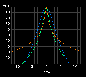 The graph of signal attenuation versus frequency for a particular tuned circuit illustrates what is called its pass-band. An example of such graphs showing the pass bands for 3 different circuits all tuned to 465kHz is generated on the right by a Java applet class called PassBand{}. It is essentially a Java version of the above C function 'DeTune()'. The red trace shows the off-tune signal attenuation produced by a single tuned circuit with a 'Q' of 1000. It is extremely sharp and is therefore suitable for receiving narrow band transmissions like morse code.
The green trace shows the off-tune attenuation produced by passing the signal through two tuned circuits in succession both of which have a 'Q' of 300.
The blue trace shows the effect of passing the signal through 4 tuned circuits in succession each of which has a 'Q' of only 100. This has a much broader peak making it suitable for speech and even music. It also provides much greater attenuation as you move away from the resonant frequency.
The source code for the above applet is available here. Please bear in mind that this was the very first applet I ever wrote in Java!
Circuit Configuration
This description of the tuning process has used a series tuned (or acceptor) circuit which is slightly easier to deal with mathematically. Receivers invariably use parallel tuned (or rejecter) circuits. The values returned by DeTune() would be the same. Only a slightly more complicated formula using a parallel resistance constant r instead of the series resistance constant R.
Other Effects
A modulated signal from a station — whether carrying speech or a morse tone — comprises a central carrier flanked by lesser sideband signals. The beats or heterodynes between the carrier signal and the sideband signals are what produce the audio frequencies in the receiver.
When the receiver is slightly off-tune from a station, the carrier will be further away from the centre of the selectivity envelope than some of the sidebands. The carrier will therefore suffer greater attenuation than the sidebands. This results in the emphasis and distortion of the higher audio frequencies, which is a familiar effect heard when a receiver is off-tune.
The DeTune() function does not cater for this effect, the simulation of which is left as an exercise and challenge for the reader!
ADF Tuning
The ADF receiver is a 3-band LF & MF receiver which has a separate control panel. The controller's tuning mechanism drives a synchro which turns the tuning capacitor in the main unit located in another part of the aircraft.
For simulation we input the output of the controller's synchro straight into the computer via an AtoD SAMP (analogue-to-digital servo amplifier). We also input the position of the controller's band switch position as a logical input. The bands covered by the ADF receiver are as follows:

The ADF receiver's synchro input is expressed as an unsigned interger ranging from 0 to FFFF for one full turn of the synchro.
The frequency to which the ADF receiver is currently tuned can therefore be calculated as shown in the following 'C' function:
long ADFfrq( struct RxData *s ) {
  int BandStart[]  = {189, 396, 830},  // kHz
      BandExtent[] = {221, 474, 990},  // kHz

      syn = r->Syn,       // current position of tuning synchro
      wb  = r->WB,        // currently selected waveband
      hi = r->SynHi[wb],  /* synchro position for high frequency
                                limit of the selected band */
      lo = r->SynLo[wb];  /* synchro position for low frequency
                                limit of the selected band */
  if(syn < lo) syn = lo;
  if(syn > hi) syn = hi;
  return((long)(BandStart +
        ((syn - lo) / (hi - lo)) / BandExtent[wb]));
}
The extent of a frequency band is unlikely to cover a complete turn of the tuning synchro. In practice it will be less. Nor is it likely to start exactly at the synchro's zero position. It will start a little beyond. The values returned by the input word for the tuning synchro for a given receiver controller have to be determined by calibration and entered into a fixed data file which is loaded on start-up. When the simulation program is started, this data is put into each receiver's RxData structure. Part of that data are the synchro input values for the upper and lower limits of each band for each receiver onboard the aircraft.
There is also an inevitable element of non-linearity in the frequency scales which ideally we should correct. This is not included in the above function but it would also be dealt with in the above function if it were dealt with at all.
Directional Information
The ADF receiver is intended for receiving non-directional beacons NDBs and radio range stations RRGs. It uses two loop aerials at right-angles to resolve the direction of a received station.
As well as an audio output, the ADF receiver has a synchro output which drives an ADF pointer on the aircraft's compass card showing the direction of the station as a compass bearing. This is how it navigates using the Non-Directional Beacons.
With a Radio Range Station, the pilot can tell which of the station's 4 quadrants he is in — north to east, east to south, south to west, west to north — according to whether he hears a Morse 'A' or a Morse 'N' being keyed. This allows the pilot to know roughly where he is in relation to the station even if the aircraft does not have direction finding capability or if their ADF function is faulty.
Signals from radio-navigation stations are received by specialised radio receivers on-board the aircraft.
There are generally 3 types of receiver as follows:

The RxData Structure
struct RxData {     // DATA STRUCTURE FOR A RECEIVER
  int Syn;          // current position of tuning synchro
  int SynHi[3];     // synchro position for highest frequency in each band
  int SynLo[3];     // synchro position for lowest frequency in each band
  int WB;           // currently selected waveband
  int Sig;          // signal strength delivered by receiver's IF amp
  int Tone[3];      // tone levels delivered to receiver's AF stage input
  int Valid;        // NAV data validation bits
  long Frq;         // frequency to which receiver is currently tuned
  double ISR;       // selected inbound VOR radial or ILS runway heading
  double OSR;       // selected outbound VOR radial
  double Brg;       // bearing of tuned station from receiver
  double RadDev;    // deviation of aircraft from selected radial
  double StrOff;    // required steering offset from station
  double ReqHdg;    // heading the aircraft must fly
  double DistTD;    // ILS distance to touch-down
  double PrvDst;    // dist to/from stn at previous program pass
  double HdgErr;    // horizontal (VOR/ILS) deviation correction command
  double GsErr;     // aircraft's ILS glideslope deviation
  double DesErr;    // difference between required and actual angle of descent
  double Atten;     // signal attenuation divisor due to receiver being off-tune
  BOOL dFrq;        // set TRUE by Receivers() when receiver is re-tuned
  BOOL capture;     // indicates a selected radial has been captured
  BOOL OnOff;       // receiver's on/off switch
  BOOL CctBrk;      // receiver's d/c power supply circuit breaker
  BOOL SynBrk;      // receiver's synchro a/c power supply circuit breaker
  struct TxData *t; // pointer to the TxData structure of the
}                   // dominant currently on-tune station.
  *Rx[10];          // Array of pointers to NumRx receiver data structures
To access the Rx[ ] pointer-array efficiently within for() loops we use a secondary array of pointers pRx[ ] which contains pointers to the elements of the Rx[ ] array:

pRx[ ] is declared inside the RxSig() function where it is used exclusively.
The following function determines the signal strength for all receivers of the type which receives the type of station whose TxData is pointed to by 't'. It also calculates the possible separate audio tone levels for each of the three possible pitches of 1020Hz, 1300Hz and 3000Hz.
int RxSig(t) {
  int RxType[] = {  // Type of Stn received by Type of Rx
    0,              // 0       NDB              0      ADF
    0,              // 1       RRG              0      ADF
    1,              // 2       VOR              1      NAV
    1,              // 3     VOR/DME            1      NAV
    1,              // 4       ILS              1      NAV
    1,              // 5     ILS/DME            1      NAV
    1,              // 6       DME              1      NAV
    2,              // 7       AMK              2      MKR
    2,              // 8       BMK              2      MKR
    2,              // 9       OMK              2      MKR
    2,              // 10      MMK              2      MKR
    2               // 11      IMK              2      MKR
  };


  // An array of pointers to pointers to RxData structures

  struct RxData
    **pRx[] = {
      Rx,      // points to Rx[] element ptg to RxData for ADF1
      Rx + 4,  // points to Rx[] element ptg to RxData for NAV1
      Rx + 8,  // points to Rx[] element ptg to RxData for MKR1
      Rx + 10  // points to the element beyond end of Rx array
    },
    *r,       // points to RxData struct of rx being dealt with
    **rx,     // points to element of Rx[] containing 'r'

    **RX,     /* This pointer points to the element of Rx[] after the one
                 containing the pointer to last RxData structure for the
                 type of receiver concerned. */

    /* The final pointer points to the element within pRx[] (above) which
       points to the element within Rx[ ] which points to the RxData structure
       of the first receiver of the type which receives the type of station
       whose TxData structure is pointed to by 't'. */

    ***prx = pRx + *( RxType + t->StnType );


  /* FOR EACH RECEIVER OF THIS TYPE, IF Rx[rx] contains a pointer to an exist-
     ing RxData structure AND if this receiver has been re-tuned since the
     last station scan, THEN cancel the 'frequency changed' flag and get its
     detuning attenuation divisor. */

  for(rx = *prx, RX = *(prx + 1); rx < RX; rx++) {
    if(((r = *rx) > NULL)) && ((r->dFrq == TRUE)) {
      r->dFrq = FALSE;
      r->Atten = DeTune(t->Frq, r-Frq);
    }

    /* Get the signal strength of this station at the aircraft and divide it
       by the de-tuning attenuation of receiver's passband. Rescale it from a
       floating point double to an interger ranging from 0 to 255. If the res-
       ulting signal is the strongest so far encountered during this station
       scan THEN set it as receiver's current signal strength, and set this
       station as dominant on-tune station. */

    if((Sig = (int)(255 * TxSig(t)/r->Atten)) > r->Sig) {
      r->Sig = Sig; r->t = t;

      /* If the station's Morse key is down, and this is the strongest station
         keying at this pitch, make this the sound level for this pitch of
         tone. */

      if((t->MorseKey == TRUE) && (r->Tone[t->pitch] < Sig))
        r->Tone[t->pitch] = Sig;
    }
  }
}
This function checks each receiver's on/off switch and dc power circuit breaker and then determines the frequency to which it is currently tuned. If the receiver has been retuned since the last pass, the new frequency is stored and a 'frequency changed' flag is set in the receiver's RxData structure. If the receiver is switched off or its circuit breaker is out, its frequency is set to zero. The signal and tone levels of all receivers are reset to zero ready for the next station scan.
void RxInput() {
  long(*GetFrq[])(struct RxData *) = {
    ADFfrq, ADFfrq,  // function returning ADF rx frequency
    ADFfrq, ADFfrq,
    NAVfrq, NAVfrq,  // function returning NAV rx frequency
    NAVfrq, NAVfrq,
    MKRfrq,MKRfrq    // function returning Marker frequency
  };
  struct RxData *r;  // points to RxData of current rx
    **rx;            // ptr to Rx[] element holding 'r'
    **RX = Rx + 10;
  static int r = 0;  // element number of Rx[] range 0 to 9
  long frq;          // current receiver frequency
  register n = 0;    // element number of Rx[]

  for(rx = Rx; rx <= RX; rx++, n++) {  // for all possible receivers
    if((r = *rx) > NULL) {    // if an rx is installed in this 'position'
      if(r->CctBrk == TRUE    // if rx's dc circuit breaker closed
      && r->OnOff == TRUE) {  // and rx is switched on
        if((frq = (*(GetFrq + rx))(r)) != r->Frq) {  // if rx has been retuned
          r->Frq = frq;       // store new frequency
          r->dFrq = TRUE;     // indicate that it has changed
        }
      } else r->Frq = 0;      // frequency = 0 means rx inoperative
    }
    r->Sig = 0;               // clear the dominant signal strength
    for(register x = 0; x < 3; x++)
      r->Tone[x] = 0;         // clear the Morse tone levels
  }
}
Transmitter Simulation
The function below simulates the activity of all active stations by controlling the keying of their callsigns and computing their signal strengths and audio tone levels presented to each receiver.
Whenever a station's Morse tone duration timer expires, the Transmitters() function reloads the station's Morse tone duration timer with the duration of the next dot, dash, inter-element, inter-letter or delay specified in its callsign string and flips the state of the Morse key from tone-on to tone-off or vice versa. This function should be called roughly every 200 milliseconds.
void TxScan() {                 // NAVIGATION STATION SCANNER
  static double Sigma, InvDst;  // For computing height of
  static int N;                 // ground under aircraft.
  static struct TxData **tx;    // Pointer to an element in
                                // Tx[ ] pointer array.
  struct TxData *t;             // Pointer to a TxData (ie a
                                // station data) structure.

  for(tx = Tx; tx <= TxHi; tx++) {   // for each element in Tx[] pointer array
    if(((t = *tx) > NULL)            // If it contains a ptr to a TxData struct
    && (--(t->MorseTimer) < 0)) {    // & it's the end of current Morse element
      t->MorseKey = !(t->MorseKey);  // reverse the state of the Morse key.
      if(*(t->pMorse) == '\0') {     // if end of current dots/dashes sequence
        t->pMorse = t->Morse;        // reset ptr to start of Morse Code buffer.
        if(t->Single == FALSE)       // if station has more than 1 callsig
        && ((--(t->Repeat) < 0))     // avoid possible division by zero
          SetUpCallSign(t);          // get the next part of the call sign
      }
      t->MorseTimer = *(t->pMorse)++;  // Set timer to duration of next dash/dot
    }
    RxSig(t);                   // compute stn's signal strength for each rx
    if((t->StnType == 4         // if the station is an ILS
    || t->StnType == 5)         // or an ILS/DME
    && (t->Dst > 0)) {          // and its distance is > zero
      InvDst += 1 / t->Dst;     // add inverse dist
      Sigma += t->Ht / t->Dst;  // add dist/height
    }
  }
  Air.GndHt = Sigma / (N * InvDst);  // Compute estimated height of ground
}                                    // beneath aircraft
As well as receiving Morse signals from radio navigation stations, the aircraft's receivers also derive navigational information from them.
ADF Output
ADF receivers use special aerials comprising two coils at right angles to each other to resolve the direction a received signal is coming from. This gives the pilot the direction of the received station from the aircraft.
 The bearing calculated by TxSig() is the bearing of the aircraft from the station. In spherical geometry, the bearing of the station from the aircraft is not just 180 degrees minus the bearing of the aircraft from the station as it would be on a flat landscape. Consequently, the ADF bearing must be computed separately by the DandB() function with the swap flag set to TRUE.
r->Brg = DandB( t, MaxDst, TRUE );
The direction of a station being received by the ADF receiver is then presented by a radio direction needle on the compass instrument:

VOR Output
VOR stations emit one signal which has the same phase in all directions and another signal whose phase angle varies as the direction of emission. For example, if you are south-east of the VOR station, the second signal will be 135 degrees out of phase with the first signal. By detecting the phase difference between the two signals it receives, the NAV receiver determines the aircraft's bearing from the station, t->Brg.
A VOR station is placed at an airways junction or waypoint at which a change of course is necessary. The pilot selects the radial r->ISR on which he wishes to approach the station with the intention of intercepting that radial, flying along it towards the station, and then onwards from the station along the opposite radial.
The values of r->ISR and t->Brg are passed to the navigation computer which derives from these the heading the aircraft must fly, r->ReqHdg, in order for the aircraft to make a smooth turn on to the radial so that it is travelling in line with the radial as it passes over the station.
The following diagram shows the pilot to have selected radial 300 (the line on compass bearing 300 which goes slightly north of west out from the station). So he intends to fly on his present heading of approximately north-east and then turn eastwards when he intercepts the station's Radial 300.

The pilot selects the radial he requires, r->ISR, by entering it in via his keyboard or dial switches. The NAV receiver provides the aircraft's current bearing from the VOR station, t->Brg and its current distance from the station, t->Dst.
It is uneconomic for the aircraft to start approaching the radial when it is still a long way out from the station. The navigation computer therefore maintains the value of r->ReqHdg so as to keep the aircraft flying towards the station along a straight course which is tangential to one of what are called the station's 'Circles of Capture'. These are set to have a radius R equal to that of the aircraft's smallest comfortable turning circle.
The navigation computer therefore computes the heading r->ReqHdg which the aircraft must fly by working out the steering offset r->StrOff from the station bearing r->Brg which will keep the aircraft aimed at the edge of the circle on the side of the selected radial closest to the aircraft. When the aircraft reaches the edge of the circle, it follows the circumference on to the selected radial, r->ISR until it reaches the station. It thus intercepts the selected radial at the station. At this point it is said to have captured the radial.
Once the aircraft has passed over the station, it must fly along outbound radial, r->OSR, the 180º projection of the inbound selected radial, r->ISR. The required heading, r->ReqHdg must be maintained to bring the aircraft smoothly back on to r->OSR whenever it drifts off. After capture, the navigation computer therefore determines r->ReqHdg in a different way as follows:

Being referenced to r->Brg, the bearing of the station from the point of view of the aircraft, the above formula takes account of spherical geometry and so works at long distance as well as short distance.
A slight problem is that when the aircraft passes over the station, it always in fact passes it a small but nonetheless finite distance to one side or the other causing r->Brg to whip suddenly through 180º. The resulting value of r->ReqHdg from the above formula therefore causes the aircraft to leave the station in what can amount to any direction. This is overcome by imposing a reasonable upper limit on the steering offset r->StrOff.
The GetReqHdg() Function
The following 'C' function simulates the navigation computer's function which computes the required heading. The required heading r->ReqHdg has nothing to do with the aircraft's actual current heading.
double GetReqHdg(struct TxData *t, struct RxData *r) {
  #define R 40     // radius of aircraft's minimum turning circle
  #define RR 1600  // square of this radius
  double a,        // used for intermediate angular quantities
    b, c, e,       // sides of construction triangles see diagram
    d = t->Dst;    // distance between aircraft and waypoint
  BOOL f = FALSE;  // to indicate whether to use + or − root

  /*If the aircraft has not so far reached the station and it is now closer
    than (within) the radius of the minimum turning circle and it is now
    receding from the station then it is deemed now to have passed station. */

  if(r->capture == FALSE && d < R && d > t->PrevDst)
    r->capture = TRUE;

  /*If the aircraft has not yet reached the station then get its deviation
    from the selected radial, determine which side of the radial it is, and
    finally find b and c (see Pre-capture diagram).*/

  if(r->capture == FALSE) {
    r->RadDev = (a = BipAng(t->Brg - r->ISR));
    if (a < 0) { a += Pi; f = TRUE; }
    b = R * cos(a); c = d - R * sin(a);

    /*If the aircraft is outside the minimum turning circle compute the square
      root of the appropriate sign, then compute the rationalised required
      heading it must fly.*/

    if((e = b * b + c * c - RR) > 0) {
      e = sqrt(e); if(f == TRUE) e = -e;
      r->ReqHdg = RatAng(r->Brg + (r->StrOff = atan(R/e)- atan(b/c)));
    }

  } else {  // else the aircraft has passed the station

    // compute a and b (see the Post-capture diagram).
    r->RadDev = (a = BipAng(t->Brg - r->OSR));
    a = r->Brg - a - a - Pi;

    r->StrOff = (b = BipAng(r->OSR - a));  // Get steering offset
    if (b > +1) a = r->OSR + 1;            // and limit it to +/-
    if (b < -1) a = r->OSR - 1;            // one radian.
    r->ReqHdg = RatAng(a);
  }
  return(r->ReqHdg);  // return the aircraft's required heading
}
When adding and subtracting a number of angles, some of which could be compass bearings and some of which could be deviations from reference lines, we can end up with very large angular quantities which can be positive or negative. Many mathematical functions can only accept angles from 0 to 2pi or from -pi/2 to +pi/2. So we need to be able to rationalise and polarise angles.
These two tasks are done by RatAng() and BipAng() below which should appear before (or at least prototyped before) GetReqHdg():
// Put a wild angle in range 0 to 2pi
double RatAng(double theta) {
  while(theta < 0) theta += TwoPi;
  while(theta > TwoPi) theta -= TwoPi;
  return(theta);
}

// Make a wild angle bipolar
double BipAng(double theta) {
  while(theta < -Pi) theta += TwoPi;
  while(theta > Pi) theta -= TwoPi;
  return(theta);
}
Although not used in GetReqHdg(), later on we will also need to be able to make sure that an angle such as a corrective deviation cannot exceed an operating limit. This is done by LimAng(), which for completeness is shown now below:
// Impose an upper and lower limit on a bipolar angle
double LimAng(double theta, double limit) {
  if(theta < 0) {
    if(theta < -limit) theta = -limit;
  } else if(theta > limit) theta = limit;
  return(theta);
}
To prove that GetReqHdg() will correctly give the heading the aircraft must follow to bring it to a smooth intercept of the selected radial, the following Microsoft Windows program uses the same formulae to trace out the trajectory of the aircraft for every possible radial from 0 to 360°.
Use the generic Microsoft Windows program Output.C in the Windows SDK Guide To Programming. Define and declare the RxData and TxData structures Rx and Tx plus the following at the beginning of the source file:
HPEN hBlackPen, hWhitePen, hYellowPen;
  HBRUSH hWhiteBrush, hBlueBrush;
  int th;         // text height (leading)
In MainWndProc(), modify the WM_PAINT, WM_CREATE and WM_DESTROY cases as follows:
case WM_PAINT:
    hDC = BeginPaint(hWnd, &ps);
    GndTrk(hWnd, hDC);
    EndPaint(hWnd, &ps);
  break;

  case WM_CREATE:
    hBlackPen   = GetStockObject(BLACK_PEN);
    hWhitePen   = CreatePen(PS_SOLID, 3, RGB(255,255,255));
    hYellowPen  = CreatePen(PS_SOLID, 1, RGB(200,200,0));
    hWhiteBrush = GetStockObject(WHITE_BRUSH);
    hBlueBrush  = CreateSolidBrush(RGB(0,0,119));
  break;

  case WM_DESTROY:
    DeleteObject(hBlackPen);
    DeleteObject(hWhitePen);
    DeleteObject(hYellowPen);
    DeleteObject(hWhiteBrush);
    DeleteObject(hBlueBrush);
    PostQuitMessage(0);
  return(NULL);
Then add the following at the end of the generic source file:
  #define Pi 3.1415926535
  #define TwoPi 6.2831853070
  #define PiBy2 1.5707963267
  #define DegRad 57.29577	// No of degrees in a radian
Put RatAng() and BipAng() in here followed by the digital read-outs display function:
ShowDeg(HDC hDC, int n, double a) {
  extern int th;
  RECT rcTextBox;
  char s[8];
  int i;
  if (n < 12)                    // If not displaying distance
    a *= DegRad;                 // then convert to degrees
  i = a; if ((a -= i) > .5) i++;
  sprintf(s, " %3.3d", i);
  SetRect(
    &rcTextBox, 120, 10 + th * n, 170, TOP + th * (n + 1)
  );
  DrawText(hDC, s,strlen(s), &rcTextBox,
           DT_RIGHT | DT_NOPREFIX | DT_NOCLIP);
}
Finally, put in GetReqHdg()'s exerciser, GndTrk():
void GndTrk(HWND hWnd, HDC hDC) {
  #define X 400    // in logical pixels
  #define Y 152    // in logical pixels
  #define TD 140   // distance of touchdown beyond station
  #define R 40     // Radius of turning circle
  extern int th;
  extern HPEN hBlackPen, hWhitePen, hYellowPen;
  extern HBRUSH hWhiteBrush, hBlueBrush;
  struct TxData *t = &Tx;  // can't pass externally-declared ptrs
  struct RxData *r = &Rx;  // internally-declared ptrs are auto!
  int SelRad, x, y;        // SR in degrees, co-ords of aircraft
  double a, b, isr, xx, yy, x1, y1, x2, y2;
  char s[24], ToFrom;
  TEXTMETRIC tm;
  GetTextMetrics(hDC, &tm);
  th = tm.tmExternalLeading + tm.tmHeight;
  y  = 10; strcpy(s,"AIRCRAFT TRACK FOR");
  TextOut(hDC, 10, y, s, strlen(s));
  y += th; strcpy(s,"AUTOMATIC CAPTURE ");
  TextOut(hDC, 10, y, s, strlen(s));
  y += th; strcpy(s,"OF WAYPOINT RADIAL");
  TextOut(hDC, 10, y, s, strlen(s));
  y += th;
  y += th; strcpy(s,"Selected Radial" );
  TextOut(hDC, 10, y, s, strlen(s));
  y += th; strcpy(s,"Aircraft Bearing");
  TextOut(hDC, 10, y, s, strlen(s));
  y += th; strcpy(s,"Radial Deviation");
  TextOut(hDC, 10, y, s, strlen(s));
  y += th;
  y += th; strcpy(s,"Station Bearing" );
  TextOut(hDC, 10, y, s, strlen(s));
  y += th; strcpy(s,"Steering Offset" );
  TextOut(hDC, 10, y, s, strlen(s));
  y += th; strcpy(s,"Required Heading");
  TextOut(hDC, 10, y, s, strlen(s));
  y += th;
  y += th; strcpy(s,"Distance");
  TextOut(hDC, 10, y, s, strlen(s));
  for(SelRad = 0; SelRad <= 360; SelRad++) {  // for each of the 360 degrees
    r->ISR = (isr = SelRad / DegRad);
    r->OSR = RatAng(isr + Pi);
    // FORM AND CLEAR THE GROUND TRACK DISPLAY RECTANGLE
    SelectObject(hDC, hBlackPen);
    SelectObject(hDC, hBlueBrush);
    Rectangle(hDC, X - 220, Y - 150, X + 150, Y + 150);
    // DRAW THE RED & GREEN CIRCLES
    a = isr + PiBy2; x1 = R * sin(a); y1 = -R * cos(a);
    a = isr - PiBy2; x2 = R * sin(a); y2 = -R * cos(a);
    for (b = 0; b <= TwoPi; b += .017453292) {
      xx = X + R * sin(b); yy = Y + R * cos(b);
      SetPixel(hDC, x = x1 + xx, y = y1 + yy, RGB(255,0,0));
      SetPixel(hDC, x = x2 + xx, y = y2 + yy, RGB(0,255,0));
    }
    // DRAW THE SELECTED RADIAL LINE IN YELLOW
    SelectObject(hDC, hYellowPen);
    x = TD * sin(isr); y = -TD * cos(isr);
    MoveTo(hDC, X - x, Y - y);
    LineTo(hDC, X + x / 2, Y + y / 2);
    // DRAW A WHITE BLOB TO REPRESENT THE WAYPOINT
    SelectObject(hDC, hBlackPen);
    SelectObject(hDC, hWhiteBrush);
    Ellipse(hDC, X - 5, Y - 5, X + 5, Y + 5);
    // PLOT THE AIRCRAFT TRACK
    xx = -210; yy = 0;          // starting position of aircraft
    t->PrevDst = (t->Dst = sqrt(xx * xx + yy * yy) + 1) + 1;
    SelectObject(hDC, hWhitePen);
    MoveTo(hDC, x = X + xx, y = Y + yy);// move to starting posn
    r->capture = FALSE;         // not yet reached the station
    while(((a = t->Dst) < t->PrevDst && a > R) || a < TD) {
      t->PrevDst = a;
      t->Dst = sqrt(xx * xx + yy * yy); //initial dist from stn
      r->Brg = RatAng((t->Brg = RatAng(atan2(xx, yy))) + Pi);
      xx += sin(a = GetReqHdg(t, r));  // update aircraft's posn
      yy += cos(a);
      LineTo(hDC, x = X + xx, y = Y - yy); // plot its position
                                           // on the screen
      ShowDeg(hDC,  4, r->ISR);
      ShowDeg(hDC,  5, t->Brg);
      ShowDeg(hDC,  6, r->RadDev);         // Radial Deviation
      ShowDeg(hDC,  8, r->Brg);
      ShowDeg(hDC,  9, r->StrOff);
      ShowDeg(hDC, 10, r->ReqHdg);
      a = t->Dst;
      if (r->capture == FALSE) a = -a;
      ShowDeg(hDC, 12, a);
    }
    for(b = 0; b < 3000; b++);             // delay
  }
}
I have since implemented this demonstration as a Java applet.
We now have to write some functions to deal with both the linear and rotational motion of the aircraft. To do this we first need a time reference.
Elapsed Time
It has been assumed that this software is called every 200 milliseconds. In a Microsoft Windows environment, however, it has been found that timer messages and call-backs can be most irregular and missed out altogether. Time-dependent operations involving speed and rate of turn and such like must be computed with reference to the true elapsed time since the previous pass of the program.
PC system time in Unix-based operating systems is provided in a time structure which contains among other quantities a double containing the number of seconds which have elapsed since the 1st January 1970 [1980 in Microsoft Windows], and an int containing the number milliseconds through the current second. In the function below we access these and combine them into a double giving the number of seconds (to 1 millisecond precision) which have elapsed since the last time the function was called.
double ElapsedTime() {    // elapsed time since previous pass
  static struct timeb T;  // System time at last program pass
  static double
    PrevTime = 0;         // absolute system time at last pass
    ElapsedTime = 0;      // elapsed time since previous pass
  double CurrentTime;     // absolute system time this pass
  ftime(&T);              // get current system time

  CurrentTime = T.time + ( (double)T.millitm ) / 1000;
  if(PrevTime > 0) ElapsedTime = CurrentTime - PrevTime;

  PrevTime = CurrentTime; // previous time ready for next pass
  return(ElapsedTime);    // return number of seconds +- 1ms
}
Rate of Turn
To be able to turn the aircraft smoothly on to its required heading, the navigation computer instructs the autopilot to roll the aircraft to give it an appropriate rate-of-turn. An aircraft's rate-of-turn is essentially a function of its roll angle — how far it is tilted sideways. A simplified view of how an appropriate rate-of-turn is determined from a given heading error is as follows:

The following function stands in place of a full autopilot, airframe, engines and flight dynamics simulation for the type of aircraft concerned. We pass to it the current heading error (HdgErr) and the elapsed time (et) since it was last called, and it returns the aircraft's average rate-of-turn since it was last called.
double GetRot(double et, double HdgErr) {  // get rate of turn

  #define RollHdgErr 0.03  // Required roll per unit hdg error
  #define RollMax    0.03  // Max allowed roll angle (radians)
  #define RollDamp 0.02    // Rate-of-change of roll damping factor

  // Rate-of-turn per unit roll (radians per second per radian)
  #define RotRoll  1.00

  double dRoll = RollDamp * et
               * (LimAng(RollHdgErr * HdgErr, RollMax) − Air.Roll);

  Air.Roll += dRoll;       // update aircraft's roll angle

  // Return average rate of turn since last program pass
  return(RotRoll * BipAng(Air.Roll - dRoll / 2));
}
Instrument Deviation
A quick aside here to define an ancillary function which is used later in the global position calculation.
A heading error is presented to the pilot as an instrument needle deviation. This deviation is made to be non-linear to make the reading more sensitive the smaller the error. The non-linear formula used is y = sin( Err / 2 ) shown below:

The following function uses this formula to return the appropriate instrument needle deviation (on a -100 : 0 : +100 scale) for a given angular error in the range from -π to +π:
int GetDev(double theta) {       // Get Deviation Angle
  return
  ((int)(100 * sin(theta / 2));  // scaling factor -100 to +100
}
This same function is used also for presenting the aircraft's glideslope error, GsErr, to show how far the aircraft is off the glideslope in the vertical plane.
Global Position

The function below in effect simulates the action of a basic GPS receiver. Given the aircraft's current position, speed and heading, it computes the aircraft's new position, heading and rate-of-turn based on the time that has elapsed since the previous program pass.
/* Compute aircraft's heading error and store
   it as a non-linear instrument deviation. */

void HorzSteer(struct TxData *t, struct RxData *r, double et) {

  r->HdgErr = GetDev(double HdgErr = BipAng(ReqHdg(t, r) - Air.Hdg));

  /*Compute & store aircraft's average rate-of-turn and from that compute its
    incremental change in heading since last time this function was called.*/

  double dHdg = (Air.Rot = GetRot(et, HdgErr)) * et;

  double AveHdg = Air.Hdg + dHdg / 2;  /* Compute aircraft's average heading
                                          since last program pass. */
  Air.Hdg = RatAng(Air.Hdg + dHdg);    // Update the aircraft's actual heading
  double dDst = Air.Spd * et;          // Compute distance aircraft has moved
                                          since last program pass. */
  double dLat = dDst * cos(AveHdg);    /* Compute change in aircraft's
                                          latitude since last pass. */

  Air.Lat += dLat;  // Update aircraft's latitude and longitude
  Air.Lng += dDst * sin(AveHdg) / cos(Air.Lat + dLat / 2);
}
Air.Spd is in Earth-radians per second so d * sin(Air.Hdg) is in Earth-radians. Dividing this by cos(average latitude of aircraft during time of travel) gives the true longitude increment. Air.Spd is the true ground speed and Air.Hdg is the true direction in which the aircraft is moving along its ground track. This need not be the direction the aircraft is pointing since wind may be causing sideways drift.
Ground Height Computation
The estimated ground height under the aircraft is derived from the ground heights of local ILS stations or height reference features. The significance of a particular ILS station's height is deemed to be inversely proportional to its distance from the aircraft: ie the nearer the ILS station is to the aircraft, the more relevant is its height for estimating the height of the ground beneath the aircraft.

The following ground height function is illustrative only. The ground height computation is in fact built in as part of the function TxScan().
void GndHt(
  struct TxData *t,             // pointer to this station's data structure
  int n                         // total number of in-range stations
) {
  static double Sigma, InvDst;  // summation variables
  static int N;                 // ILS station count
  N++;                          // increment Nº of ILS stns considered
  if(t->Dst == 0)               // if aircraft directly over an ILS stn
    Air.GndHt = t->Ht;          // height of ground = height of station
  else {                        // else continue the summations
    InvDst += 1 / t->Dst;
    Sigma += t->Ht / t->Dst;
    Air.GndHt = Sigma / (N * InvDst);
  }
}
To navigate effectively, an aircraft's flight control system must know its pitch, roll and bearing relative to the ground. This is provided by a device containing one or more spinning flywheels equipped with tilt sensors.
Gyro Platform

The bottom synchro is a stable gyro reference platform upon which rests an error synchro which corrects the compass card to the Earth's magnetic field. The card position is monitored by the upper synchro which takes into account the fact that the card can be turned manually as well as by the error synchro. Gyrocompass is simulated by the following 'C' function (excluding circuit breaker logic):
void Gyro(double et) {
  #define T       ????          // annunciator's tick-tock constant
  #define FSD     ????          // annunciator's full-scale deflection
  #define HALFDEG .008725       // ½° in radians
  #define ERRDEC .002908333     /* 10°/min card error decrement constant
                                   in radians/second */
  static int AnnDecr = T;       /* Use Annunciator tick-tock constant
                                   as iterative decrement */

  /* If the compass card is within half a degree of indicating the correct
     magnetic heading, make the annunciator tick-tock, otherwise set it to
     full scale deflection. */

  if((double CardErr = BipAng(Air.CardHdg - Air.Hdg - Air.MagVar)) < HALFDEG) {
    if(Air.Ann > +FSD)          // if annunciator > full scale +ve
      AnnDecr = -T;             // make deflection decrementer -ve
    else if(Air.Ann < -FSD)     // if annunciator < full scale -ve
      AnnDecr = +T;             // make deflection decrementer +ve
    Air.Ann += AnnDecr * et;    // Decrement annunciator by the
  }                             // amount of the tick-tock constant
  else Ann = FSD;               // else set annunciator to full scale deflection
  double ErrDec = ERRDEC * et;  /* The amount by which to decrement
                                   the card error this program pass */
  if(CardErr > 0)               // a +ve error requires a -ve
    ErrDec = -ErrDec;           // decrement and vice versa
  Air.CardHdg += ErrDec;        // advance card heading towards magnetic heading
}
Pitch & Roll
Pitch and roll information is provided by 3 gyro platforms:
  System 0   the auxiliary gyro
  System 1   the captain's main gyro
  System 2   the first officer's main gyro
The auxiliary can be switched in place of either of the other gyros. The transfer switch is a 28 volt dc relay supplied through its own circuit breaker. Each gyro is powered from the appropriate 115 volt ac bus via its own circuit breaker.
The captain and first officer each have an attitude reference indicator containing a sphere which shows the current attitude (pitch and roll) of the aircraft. These are each powered through their own circuit breakers from the appropriate 115 volt ac bus. If an instrument or the gyro supplying it with attitude information is off or faulty, a physical warning flag drops into view within the instrument window.
 The captain or first officer can check the integrity of his gyro and instrument synchros by putting it through a 'precess' cycle. This causes the sphere to precess exponentially from the level-flight indication to an indication of 90-degrees of both pitch and roll. The precess cycle, as illustrated by the adjacent graph, takes about 10 seconds to complete.
Assuming the equipment is working properly, the sphere then drops back to indicate the aircraft's current pitch and roll. The precess cycle is controlled by the precess state flag as follows:
GyroState = 0  gyro just switched on or has been warm-reset
            1  gyro has erected and is working OK
            2  gyro has failed
The following data has to be maintained independently for each gyro system. The data structures for the auxiliary gyro (system 0), the captain's main gyro (system 1) and the first officer's main gyro (system 2) are accessed through the array of pointers *Gx[ ]. Data relating to the horizon instruments is in the captain's (NAV1) or the first officer's (NAV2) RxData structure as appropriate.
struct GyroData {
  int Status;     // stage in the gyro precess cycle (see above)
  double Pre[2];  // current gyro pitch & roll precess angles
  BOOL GyroCB;    // gyro's 115volt a.c. circuit breaker state
  BOOL Erect;     // TRUE = gyro erected OK, FALSE = gyro failed
} *Gx[3];
A 'C' function which simulates the gyro's precessing cycle is shown below. This function is entered separately for pitch and for roll for each gyro system.
double GyroPrecess(
  struct GyroData *g,          // pointer to data struct of Gyro 0, 1, 2
  int i,                       // pitch/roll index:  0 = pitch, 1 = roll
  double et                    // elapsed time since last program pass
) {
  #define INIT  .0001          // gyro angle at start of precess cycle
  #define K    1.5             // precess iterative multiplying factor
  double pre = *(g->Pre + i);  // gyro's current precess angle

  if(g->Status == 0) {  // If this gyro has just been switched on or reset
    pre = INIT;         // set its precess angle to its initial 'seed' value
    g->Status = 1;      // advance the gyro to its 'precessing' state
  }
  else                  // Otherwise
  if((g->Status == 1)   // if this gyro is currently in its precessing cycle
  && (pre < HalfPi)) {  // and it has not yet precessed 90 degrees
    pre *= (K * et);    // multiply its current precess angle by 90 degrees
    if(pre > HalfPi) {  // If, as a result, the precess angle has now over-
      pre = HalfPi;     // shot its 90° limit, set it to its 90° limit and
      g->Status = 2;    // advance the gyro to its 'precess completed' state
    }
  }
  *(g->Pre + i) = pre;  // Store and return the updated precess
  return(pre);          // angle ready for next pass
}
The circuit breaker and main/auxiliary gyro switching logic is dealt with by the following function. It returns an index number 'j' which indicates which gyro platform is supplying the attitude information. If we are dealing with the captain's instruments, j can be 0 or 1; if we are dealing with the first officer's instruments, j can be 0 or 2 according to whether the pilot concerned is switched to the auxiliary or his main gyro. However, if the gyro is inoperative for any reason, it returns a negative value of 'j' according to the nature of the problem.
int GyroLogic(
  int i,        // index: 0 for captain's or 1 for first officer's instruments
  double et     // elapsed time since last program pass
) {
  struct RxData *r = *(Rx + 4 + i);  /* Declare pointer to the captain's
                                        or first officer's RxData */

  if(r->TranCB == TRUE)      // If 'transfer switch' circuit breaker closed
  && (r->TranSw == True)) {  // & transfer switch is set to 'auxiliary gyro'
    r->TranLmp = TRUE;       // light the 'transferred to auxiliary' lamp
    j = 0;                   // set gyro index = 0 [for auxiliary gyro]
  } else {                   // Else
    r->TranLmp = FALSE;      // kill the 'transferred to auxiliary' lamp
    j = i;                   // set the gyro's index the same as
  }                          // the captain's or first officer's

  struct GyroData *g = *(Gx + j);  /* Declare a pointer to the data
                                      structure for the gyro in use. */

  if(g->GyroCB == FALSE)  // If relevant gyro's circuit breaker is out, set
    j =  -1;              // gyro index to show gyro platform inoperative.
  if(r->SphCB == FALSE    // if horizon circuit breaker is out
  || g->Erect == FALSE)   // or gyro platform failed to erect
    j = -2;               // set gyro index to show attitude system failed
  return(j);              // return valid gyro platform index or failure code.
}
The main attitude system function below uses the previous two functions to provide the attitude (pitch and roll) indications on the captain's or first officer's horizon display, and also displays the appropriate instrument warning flags and lights the appropriate warning lamps.
void AttitudeSystem (
int i,     // index: 0 = captain's or 1 = first officer's instruments
double et  // elapsed time since last program pass
) {
  if((int j = GyroLogic(i, et)) < -1) {  // IF CURRENT GYRO IS INOPERABLE
    r->GyroFlag = TRUE;                  // display its warning flag
    if(j < -1)                           // If gyro platform failed
       r->AttFailLmp = TRUE;             // light attitude system fail lamp
  } else {                               // ELSE THE GYRO CONCERNED IS WORKING
    r->AttFailLmp = FALSE;               // kill attitude system fail lamp
    r->Pitch = Air.Pitch;                // set sphere pitch to aircraft pitch
    r->Roll = Air.Roll;                  // set sphere roll to aircraft roll

    // If the pilot concerned is holding down 'precess test' button, then
    if(r->PreReq == TRUE) {
      r->GyroFlag = TRUE;                // show the gyro warning flag
      r->Pitch += GyroPrecess(g,0,et);   // add gyro precess pitch increment
      r->Roll += GyroPrecess(g,1,et);    // add gyro precess roll increment
    } else r->GyroFlag = FALSE;          // else hide warning flag
  }
}
At an airport, information in the horizontal plane is provided by an ILS localiser transmitter which is positioned at the opposite end of the runway from the point of touchdown.
ILS Glide Slope
The ILS functions like a VOR with the 'selected radial' permanently set to the runway heading. The angular error by which the aircraft is off the runway's extended centre line is called the localiser deviation. It is the same thing as the horizontal deviation from a VOR's selected radial, Hdev.

To calculate the glideslope deviation we must first transfer the point of reference (from which we determine the aircraft's position) from the localiser to the point of touchdown. This is to determine the distance 'x', which is the aircraft's effective distance out along the extended runway centre line.
We then switch to the vertical view and use 'x' and the aircraft's height to find the aircraft's current angle-of-approach to the point of touchdown. We then compare this with the runway's prescribed glideslope angle to find the glideslope error.
The glide slope transmitter near the runway touch-down point sends up a pair of radio beams at angles such that they have equal strength along the plane of the approach glide slope. The plane of the glide slope tilts upwards at an appropriate glide slope angle 't->GS' from the point of touch-down on the runway:

The glide slope error, GsErr is the angular difference (a - t->GS) by which the aircraft is above or below the glide-slope plane. This glideslope error signal is received by the NAV receiver when it is within 30km of the glideslope transmitter.
To be able automatically to bring the aircraft on to the glide slope smoothly we must calculate the 'required angle of descent' as shown in the above diagram:
double ReqDes(struct TxData *t, struct RxData *r) {
  #define FlairHeight .0000015  // ~9.55 metres in Earth radians
  double
    Hdev,             // aircraft's angular displacement from runway centre line
    ReqDes,           // Required angle of descent
    gs,               // runway's glideslope angle
    GsErr,            // linear version of glideslope error
    RunLen = t->Len;  // runway length

  if(Air.Ht < FlairHeight) {  // if aircraft is now below flairout height
    RunLen *= .75;            // advance touchdown point 1/4 way down runway
    gs = 0;                   // and set glideslope angle to 0
  } else gs = t->GS;          // else, use runway's actual glideslope angle

  Hdev = BipAng(t->Brg - r->ISR);  /* Compute aircraft's angular displace-
                                      ment from runway centre line. */

  /*Provided aircraft's distance along the extended runway
    centre line from current point of touchdown is non-zero: */

  if((double x = (double D = t->Dst) * cos(Hdev)) - RunLen) != 0) {

    /* Compute the glide slope error as a linear angular quantity and store
       it in RxData as an appropriately scaled instrument needle deviation: */

    r->GsErr = GetDev(GsErr = BipAng(double a = atan(Air.Ht / x)) - gs));

    double y = D * sin(Hdev);        // compute perpendicular dist. to runway
    r->DstTD = sqrt(x * x + y * y);  // line & distance to touchdown point
    ReqDes = BipAng(a + GsErr);      // required angle of descent
  } else {                           // ELSE, DISTANCE TO TOUCHDOWN IS ZERO
    r->GsErr = 0;                    // glideslope error indication
    r->DstTD = 0;                    // distance to touchdown point
    ReqDes = 0;                      // required angle of descent
  }
  return(ReqDes);                    // return required angle of descent
}
When the aircraft is only a few metres above the runway, it ceases to descend at the normal fixed glideslope angle, gradually reducing its angle of descent to zero in order to make a smooth landing. This is called 'flair-out'.

The function ReqDes() performs this flair-out by shifting the touchdown point a quarter of the way down the runway and changing the glideslope angle to zero once the aircraft has gone below the critical height 'FlairHeight'. The damping effect of the way GsErr is computed causes the aircraft to make a smooth curved intercept with the surface of the runway.
Vertical Steering
The next task is to make the aircraft's actual angle of descent, Air.Des, the same as the required angle of descent, ReqDes:

Assuming automatic trim etc., the angle of descent is mainly a function of the aircraft's pitch and air speed. For the most part, airspeed would not be used to actually control the angle of descent. To control the angle of descent, we are therefore concerned only with changing pitch by a small amount 'dPitch' to counter the 'error' in angle of descent, DesErr = ReqDes - Air.Des. We shall make the amount by which we change the pitch proportional to DesErr:
dPitch = K1 * ( ReqDes - Air.Des );
Because the aircraft is a large finite object with physical limitations, we must impose an upper limit, RopLim, on the rate at which we can safely change the pitch. RopLim is the limit for the rate of change of pitch and is in radians per second. The limit to which we can change pitch during the elapsed time between program passes is therefore RopLim * et radians. Therefore in response to a given angle of descent error, we update the aircraft's pitch as follows to bring the aircraft smoothly on to its correct descent path:
Air.Pitch += LimAng(K1 * BipAng(ReqDes - Air.Des), RopLim * et);
But there must be an upper limit, PitchLim, to the actual pitch itself. We must therefore split the above statement into two as follows:
dPitch = LimAng(K1 * BipAng(ReqDes - Air.Des), RopLim * et);
Air.Pitch = LimAng(BipAng(Air.Pitch + dPitch), MaxPitch);
The change in angle of descent is proportional to the change in pitch. We can therefore return a change in angle of descent as PitchDes * dPitch. The complete function for determining the change in angle of descent effected by the airframe and flight control systems in response to a given angle of descent error is:
double GetdDes(double et, double DesErr) {
  #define PitchDesErr .03  // change in pitch per unit angle of descent error
  #define RopLim .01       // rate of change of pitch limit in radians/second
  #define MaxPitch .5      // maximum permitted pitch in radians
  #define DesPitch 1.00    // change in Air.Des per unit change in Air.Pitch

  dPitch = LimAng(K1 * BipAng(ReqDes(t, r) - Air.Des), RopLim * et);
  Air.Pitch = LimAng(BipAng(Air.Pitch + dPitch), MaxPitch);
  return(DesPitch * dPitch);
}
This function is our 'dummy' standing in place of a complete airframe simulation which would compute the change in angle of descent from pitch, trim, thrust, and the many other variables affecting the result in a real aircraft.
The whole vertical steering task is managed by the following function which, from the required angle of descent and the actual angle of descent, updates the aircraft's current height and angle of descent:
void VertSteer(struct TxData *t, struct RxData, *r, double et) {

  /*Compute angle of descent error and store it
    also as a non-linear instrument deviation: */

  r->DesErr = GetDev(double DesErr = BipAng(ReqDes(t, r) - Air.Des));

  /*Compute the required incremental change in the angle of descent
    since the previous pass, then update the aircraft's angle of
    descent and hence its height since previous pass. Note that Air.Spd
    is the aircraft's horizontal ground track speed. Hence tan(). */

  Air.Ht -= Air.Spd * et * tan(Air.Des = RatAng(Air.Des + GetdDes(et, DesErr)));
}
Finally, to bring all these radio environment and navigation control functions in this document all together, they are called from the following overall navigation function which should be called regularly every 200 milliseconds.
As an exercise, this function has been headed as a timer call-back function to be called by a designated system timer within an operating system environment.
WORD FAR PASCAL Nav(  // called every 200 ms
  HWND hWnd,          // identifies the Nav window
  WORD wMsg,          // timer message resulting in this call
  int nIDEvent,       // id number of system timer which made the call
  DWORD dwTimer       // current system time
) {
  StnPoll();          // check rough distance of stations
  RxInput();          // scan receiver tuner inputs etc.
  TxScan();           // get station signal strengths

  struct RxData *r = *(*(Rx + 4) + Air.Sw); /* The NAV Rx which is currently
                                               switched to the NAV computer. */

  struct TxData *t = r->t ;       // dominant station currently being received
  double et = ElapsedTime();      // elapsed time since last pass
  if((int Sig = r->Sig) > 0)      // if in range of nav station
    HorzSteer(t, r, et);          // do horizontal (roll) steering
  if(((int st = t->StnType) == 4  // If the station is an ILS
  || st == 5)                     // or ILS/DME
  && (Sig > 85))                  // and it is within glideslope range
    VertSteer(t, r, et);          // do vertical (pitch) steering
}
For this to work you will have to set up the timer in the WM_CREATE case in the application's MainWndProc() as follows:

'C' Functions
The following schematic shows the relationships between the 'C' functions which have been discussed in these research project notes.


Circuit Breaker Logic
Within the functions discussed in these notes, many of the computations have been made conditional upon the states of various circuit breakers which control the power supplies to the various elements of the aircraft's on-board equipment. The positioning of these circuit breakers is indicated in the diagram below:

© 1997 Robert John Morton


 The graph of signal attenuation versus frequency for a particular tuned circuit illustrates what is called its pass-band. An example of such graphs showing the pass bands for 3 different circuits all tuned to 465kHz is generated on the right by a Java applet class called PassBand{}. It is essentially a Java version of the above C function 'DeTune()'. The red trace shows the off-tune signal attenuation produced by a single tuned circuit with a 'Q' of 1000. It is extremely sharp and is therefore suitable for receiving narrow band transmissions like morse code.


 The bearing calculated by TxSig() is the bearing of the aircraft from the station. In spherical geometry, the bearing of the station from the aircraft is not just 180 degrees minus the bearing of the aircraft from the station as it would be on a flat landscape. Consequently, the ADF bearing must be computed separately by the DandB() function with the swap flag set to TRUE.


 The captain or first officer can check the integrity of his gyro and instrument synchros by putting it through a 'precess' cycle. This causes the sphere to precess exponentially from the level-flight indication to an indication of 90-degrees of both pitch and roll. The precess cycle, as illustrated by the adjacent graph, takes about 10 seconds to complete.


