Considerations
Modern HF receivers are sufficiently sensitive to pick up signals from the other side of the world on the proverbial piece of wet string. To my mind, sensitivity is no longer an issue the way it was two or three decades ago.
On the other hand, the radio spectrum is much more crowded than it was 2 or 3 decades ago. We are nowadays positively bathed in an impervious smog of electromagnetic energy. Our radio environment is polluted by a plethora of television, local radio, private mobile radio and — perhaps above all — by the ubiquitous mobile telephone heads, which now litter almost every high-rise roof top and grow like trees along motorways and railway tracks. The traditional sources of interference like the car ignition, the vacuum cleaner and the washing machine are of course still with us. And what about this thing right here in front of me. It generates a constant concoction of square waves and pulse trains ranging from the 75 Hz time base of its monitor to the >2 GHz of its CPU's internal bus clock. A personal computer is not exactly Mr Clean when it comes to radio noise.
All these things contribute to the interference and noise that can potentially drown every distant signal I try to snatch from the mêlée. To my mind, therefore, it is selectivity that is now the issue.
Modern receivers are very selective. My receiver allows me to choose between a 6 kHz and a 2·5 kHz signal passband. It uses mechanical filters in the IF (intermediate frequency) section. These provide very precise and well shaped signal passbands. It is also a double conversion superhet. This pretty well guarantees that I will not get any unwanted images of strong signals from other parts of the radio spectrum.
However, when I look at the RF (radio frequency) section of my receiver — the part where the raw signal actually enters the receiver — I see only very crude filtering. It comprises only two switched filters for the whole of the LF/MF/HF range. One allows through all the RF energy coming in from the aerial that is between 100 kHz and 1·7 MHz. The other allows through all the RF energy coming in from the aerial between 1·7 and 30 MHz. That's an awful lot of unwanted energy hitting the receiver's first active device — namely its combined RF amplifier and mixer. Quite different from the old days when good HF receivers had one or two fully tuned RF amplifier stages — but these are not practical for the automatic search and scan functions demanded by today's short wave listeners.
I realise a modern active device like a MOSFET (metal oxide semiconductor field-effect transistor) can tolerate a wide range of input signal strength. Nevertheless, I am sure that presenting it with as strong and as clean a signal as possible will never do any harm and can only help when it comes to prizing a weak signal from the cacophoney of the HF radio spectrum. And this is the aerial's job.
An aerial can provide two kinds of selectivity — frequency selectivity (favouring signals within a desired frequency range) and directional selectivity (favouring signals coming from the desired direction). These two kinds of selectivity reinforce each other. Their effects add. Consequently, the best kind of aerial is one that provides both kinds of selectivity.
Choices
The text book aerial is the electric dipole. It is a length of wire laid in line with the electic vector of the desired signal. This is perpendicular (at right angles) to the direction from where the signal is coming. The wire is cut to a length that will make it electrically resonant at the frequency of the desired signal.
The field strength of the electric vector of the signal wave varies in a cycle. The wire feels only a weak electric field that gradually builds up in strength until it reaches a maximum as the wave passes by. [The strength of an electric field is measured in volts per metre.] The electric field then starts to diminish (fade) back down to zero. It then starts to grow again in the opposite direction (the opposite polarity) up to a maximum again and then starts to fade again all the way to zero. Then the cycle repeats. It repeats at the frequency of the signal.
The presence of the signal's electric field along the direction of the wire induces a potential difference between one end of the wire and the other. If the signal's electric field were 30 micro volts per metre, and the wire were 20 metres long, then there would be a voltage of 600 micro volts across the whole length of the wire. This causes a current to flow along the wire, just as if you connected a very weak battery across it.
The current comprises all the free electrons in the metal of which the wire is made being propelled to one end of the wire by the force the signal's electric field exerts upon them. The electric field rises to a peak, falls back to zero, then rises and falls again in the opposite direction — all in a repeated cycle. This causes the metal's free electrons to swill back and forth from one end of the wire to the other.
One way of visualising this is to imagine the wire as a motorway with big car parks at each end. One end is suburbia. The other end is the commercial centre of a city. People commute along the motorway each day.
The problem with the dipole, of any given length, is that it is only resonant over a very small range of frequencies. I therefore think that, in view of the vast frequency range of the HF bands, the magnetic loop or coil aerial is a much better option for the short-wave listener.
Pick-up Coils
To provide a well-defined low-noise pass-band, I have opted not to use an aerial wire or any form of rod antenna to pick up the arriving signal. Instead, I have decided to use a very large and very high-Q coil to capture the magnetic vector of the arriving signal. The magnetic vector of the arriving signal is also less prone to artificially generated radio interference. This coil is to be tuned using a section of the multi-gang variable capacitor used to tune the radio-frequency stages of the receiver. The fact that the signal pick-up device is variably tuned means that a narrower lower-noise signal is supplied to the input of the receiver.
Please note that, for me, this form of electromagnetic transducer is highly experimental and involves various magnetic materials as coil cores. It is certainly outside mainstream theory at the moment.
 The pick-up coil should be mounted with its axis vertical. This will cause it to pick up signals that are horizontally polarized electrically, which is correct for practically all transmissions on these bands. It will have a good omni-directional horizontal gain. Its tuning capacitor should be mounted quite close to it, being varied via a tort cord and pulley system ganged to the receiver's tuning capacitors. Alternatively, the capacitor could be varied via a synchro motor linked to a synchro generator mounted on the receiver's main tuning shaft. The pick-up coil can be mounted inside a building but it should be mounted as high as practicable, away from steel-reinforced walls or beams.
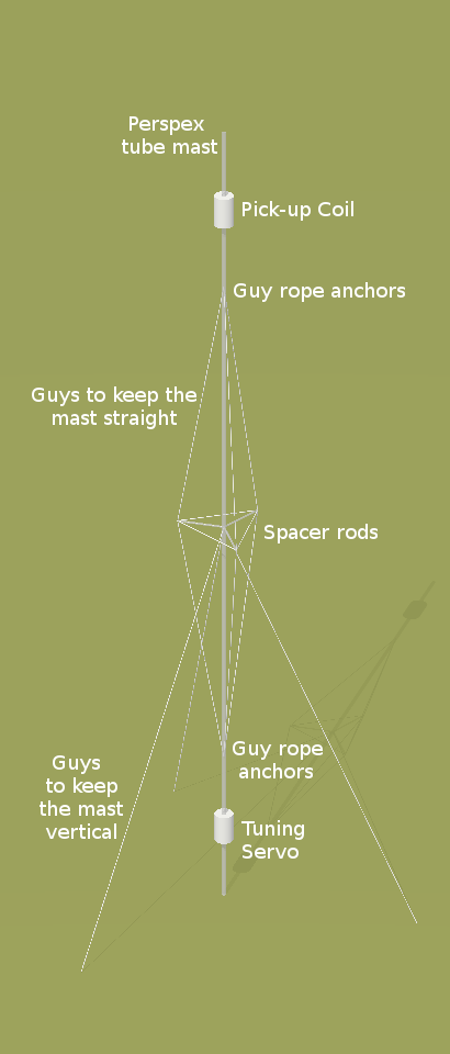
The illustration on the right shows a mast-mounted version of a pick-up coil for Top Band [160 metres: 1695 to 1957 kHz]. The 10-metre mast is a hollow perspex tube 50mm diameter. It is kept vertical by three guy ropes running 20° from the vertical and spaced 120° apart around the mast. Each guy is fixed to an anchor half-way up the mast. At this half-way point are three horizontal radials of 13mm perspex tube also spaced 120° apart but off-set from the guys by 60°. These act as spacers for three pole-guys, whose purpose is to keep the whole of the mast straight. The top short cylinder is the pick-up coil. The lower one houses the tuning control servo and feeder terminator.
The tuned circuits for the RF stages of the receiver use smaller coils with the same inductance as the pick-up coil. The parameters and dimensions for the pick-up and tuning coils can be calculated for different tuning ranges and coil dimensions using the coil calculator. For best results, all coils should be wound with Litzwire, which comprises a number of separately insulated strands of fine copper or silver wire plaited into a light composite cable.
The pickup coils described herein are not particularly efficient as regards their electromagnetic coupling with 'free space'. However, since my interest is only in reception, this is not at all a problem. For transmission, the length of the wire of the pickup coil would have to be close to the electrical wavelength for which it is to be used. This would require a different design, constrained by the practicalities of construction.
©Nov 2001 Robert John Morton
